How to Create a Site Plan Using Architect 3D©
Architect 3D Tutorials
Learn how to draw one of the most necessary drawing documents in a set of Permit Plans: the Site Plan.
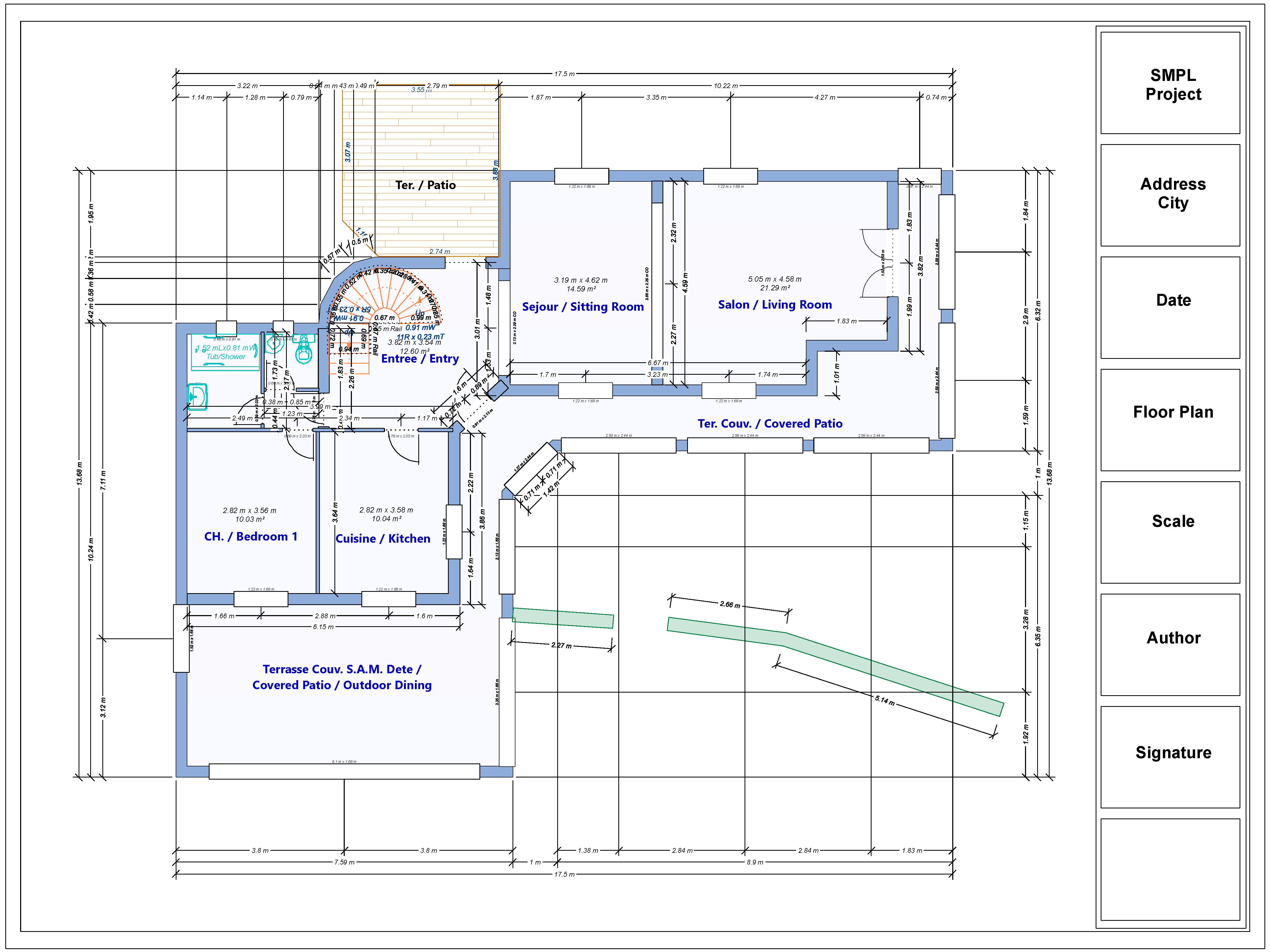
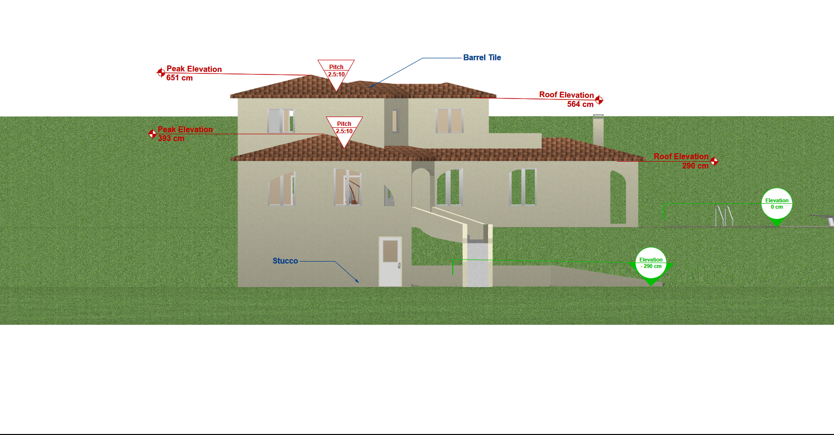
The Site Plan shows an overview of the project as a plan or aerial view, including the original conditions and restrictions of the property as well as the projected constructions, additions, etc. If you are starting the design process from the outset, you can use the information and drawings of the Floor Plan as well as the ones from your Roof Plan.
In order to create the Site Plan, we must start by importing or tracing the Plot Plan (also called Situation Map). This document is provided by different cadastral authorities as well as professional Surveyors, depending on your permit requirements and the location of your property.
Once you get the Plot Plan, let’s develop the Site Plan following these steps:
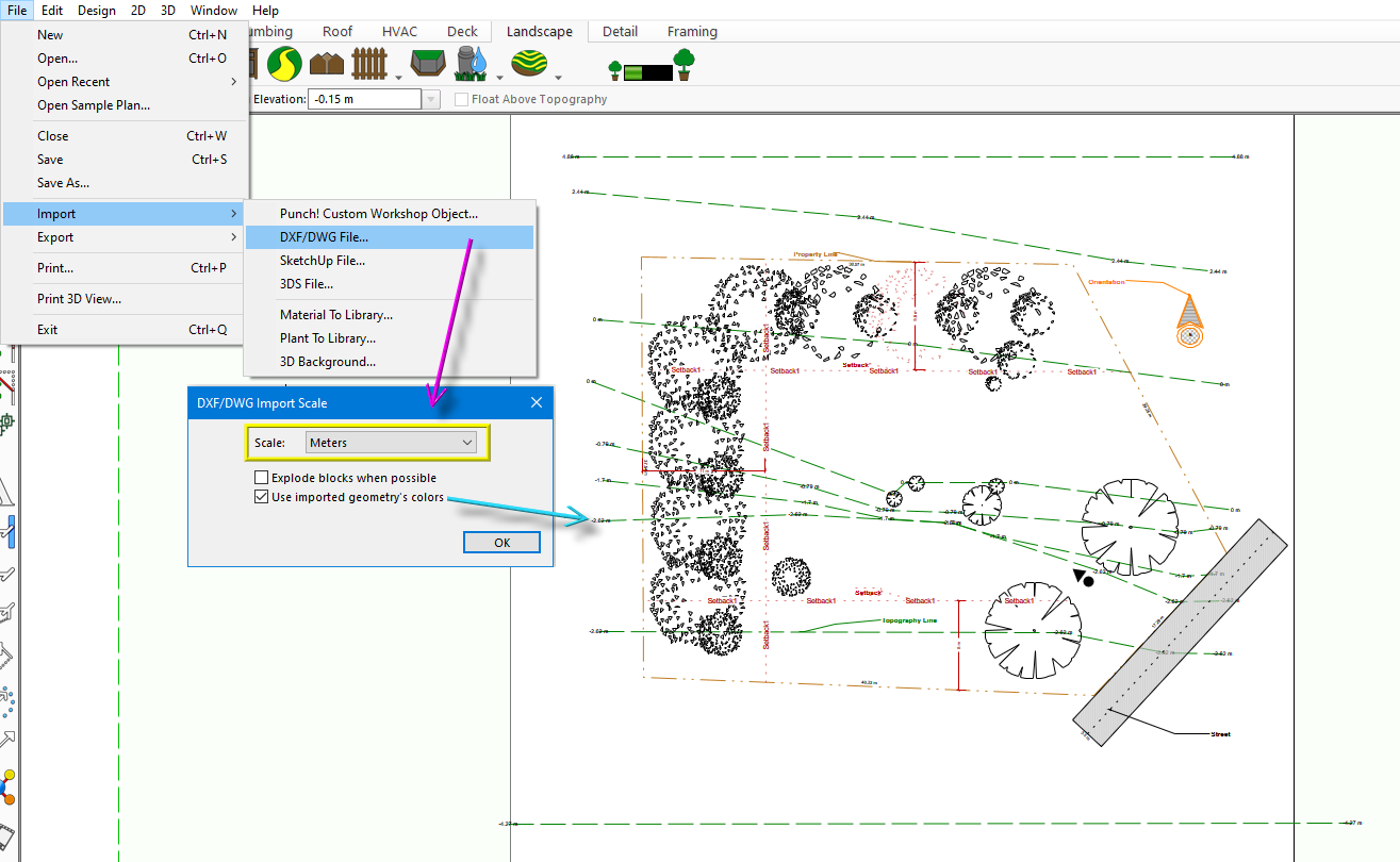
Step 1: usually, the Plot Plan is provided as a DWG file. In this case, you can import this file directly to your Architect 3D program. To do this, open your program => File => Import => DXF / DWG File => the menu will open (pointed with a magenta arrow in the image below). It is important that you set the correct scale (outlined in yellow in the image below). If the DXF / DWG file was developed using colors, select the “Use imported geometry colors” option so the imported file will show the same colors used in the original file (pointed with a cyan arrow in the image below).
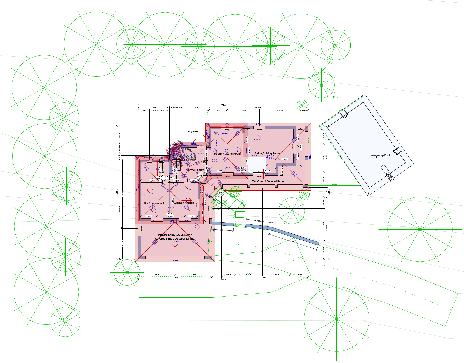
In the image below, observe the different elements included in the plan: property lines (outlining the property), topography lines (showing the different levels of the terrain), setbacks (horizontal distance between the property line and the authorized boundaries of the construction), plants, street in front of the lot, as well as the geographical orientation (North). These elements may vary for different locations.
Note that, if you have this plan as a jpg or bmp or png drawing, just proceed to import the image and trace the lines (Design => Floor Plan Trace Properties).
Step 2: once you traced or imported the Plot Plan, proceed to convert the lines and shapes to Architect 3D© components.
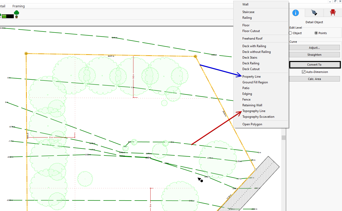
For example, select the lines indicating the levels of the terrain => the properties bar will open => Convert to => Topography line => set the elevation (pointed in red in the image below).
Another example: select the line in the perimeter of the property => the properties bar will open => Convert To => Property Line (pointed with a blue arrow in the image below) or you can convert this line to Fence.
If there are setback lines, keep them as they are in order to use them as guide for the next step.
At this point, we completed the current location and restrictions of the property.
Step 3: once the current conditions and restrictions are complete, you can proceed to draw the buildings, exterior elements, etc.
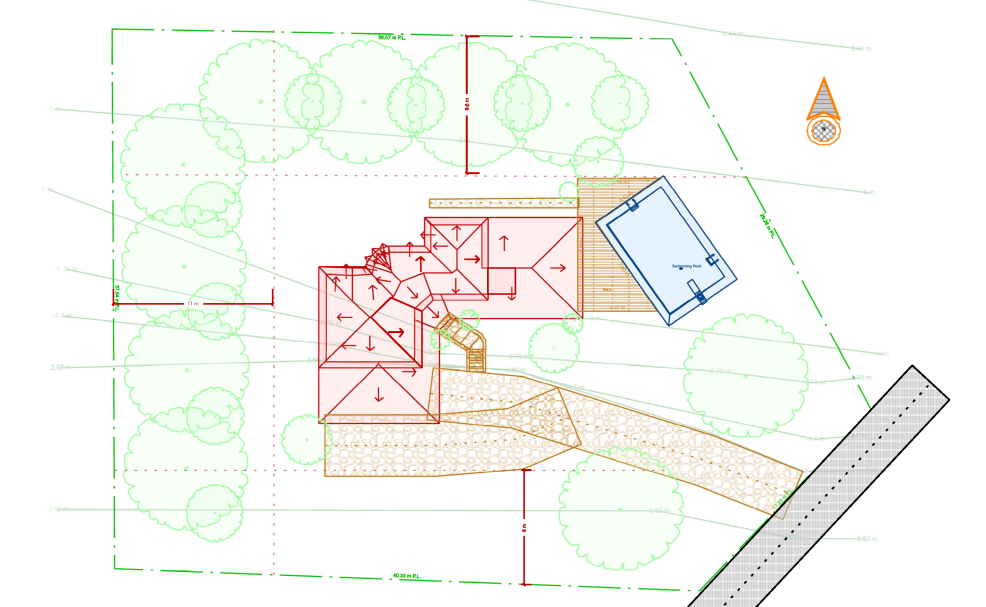
In this case, first we are adding the house Roof Plan (in red in the image below). Note that the house, as per the Floor Plan, is developed withing the setback limits.
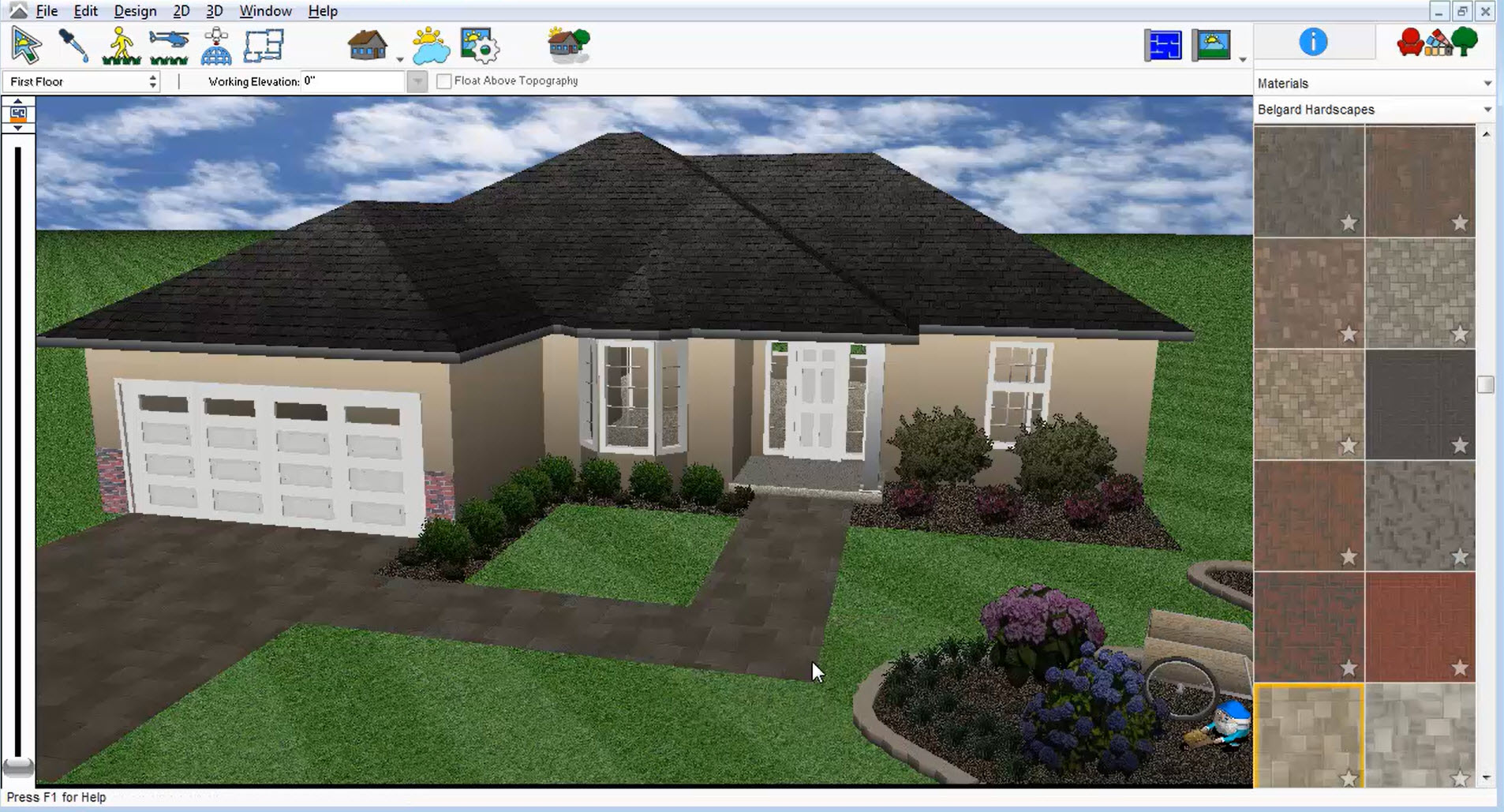
The exterior pathways, exterior stairs and deck (in brown in the image below) can be created with the Pathway and Patio tools (Landscape tab). The stair tool is in the Deck tab as well as the Floor Tab.
Another important component is the swimming pool (if it is included in the project). You can use a ready-made pool (Furnishing tab) or develop a custom pool using the Pool Designer Power Tool (if your program includes this tool)
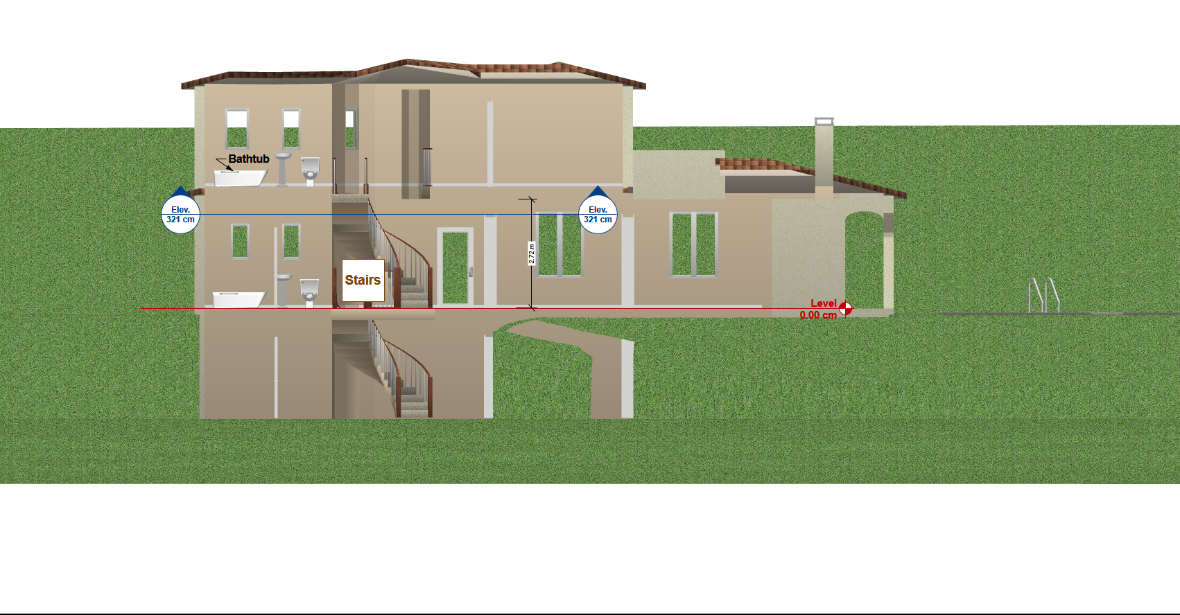
Note that you must define the elevation of each component using the elevation of the Topography lines as guide.
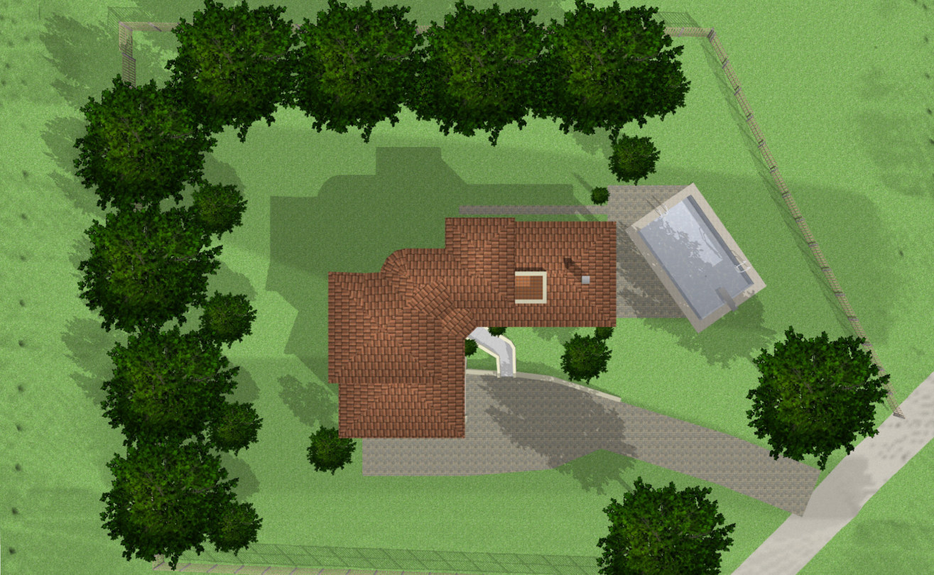
This step completes the Site Plan developed as a plan.
Step 4: if you wish to submit your Site Plan as an aerial view, Architect 3D includes the perfect tool for this job: 3D => 3D Navigation => Aerial View.
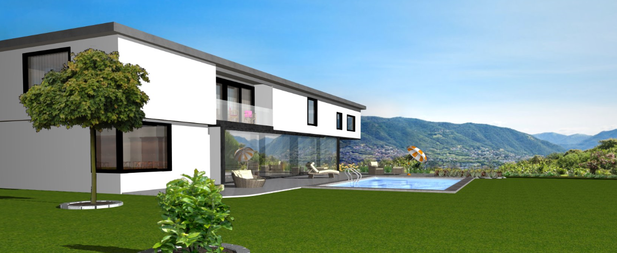
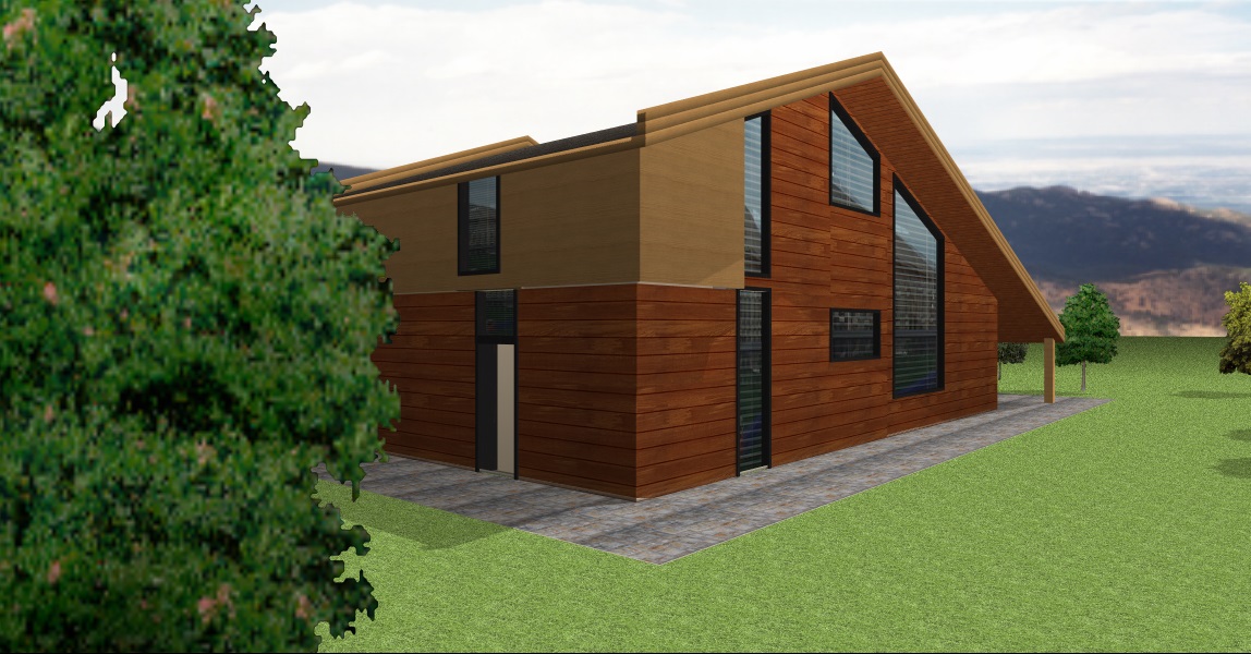
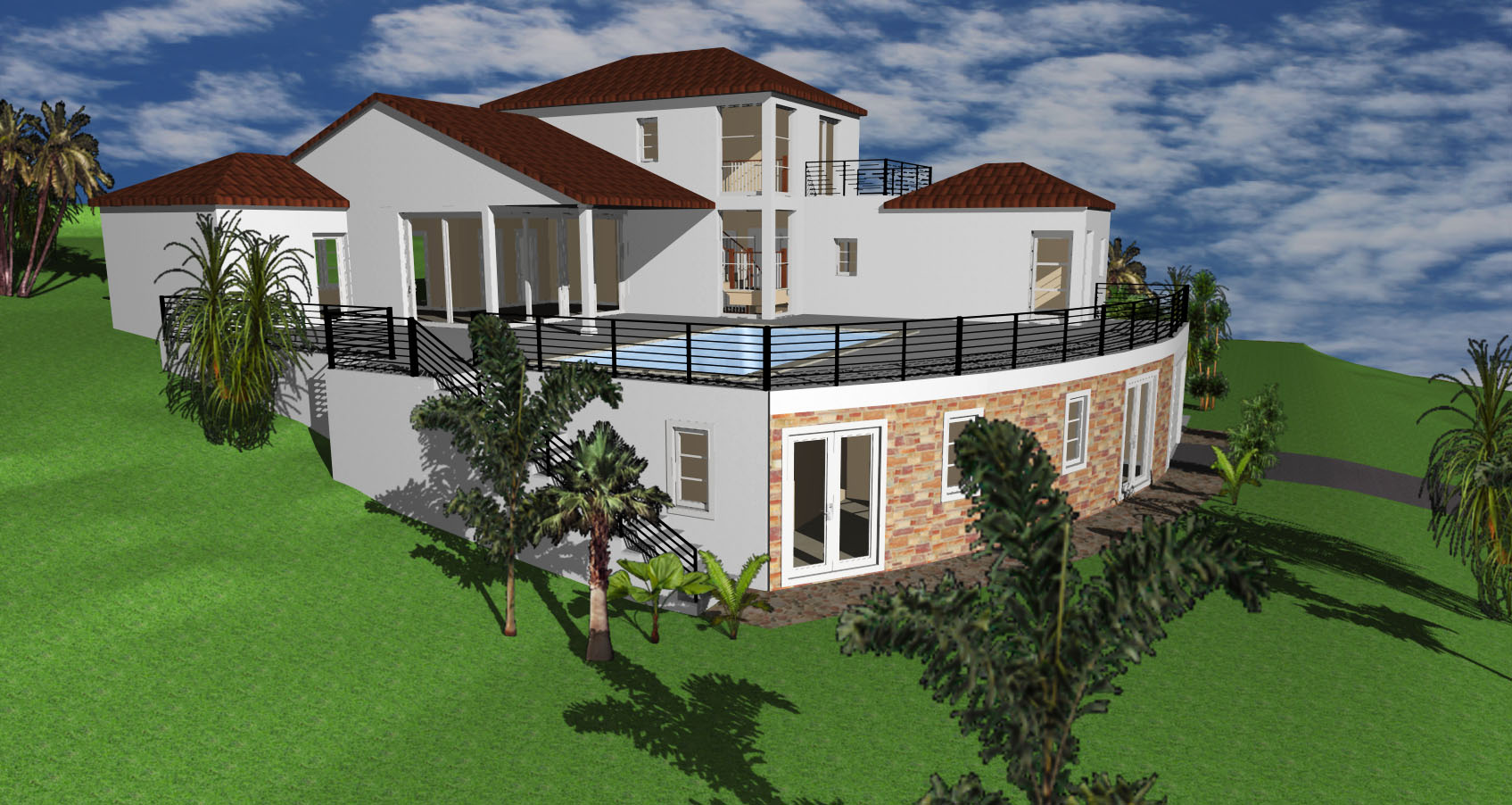
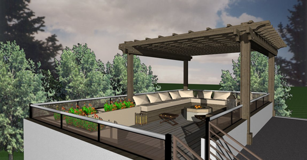
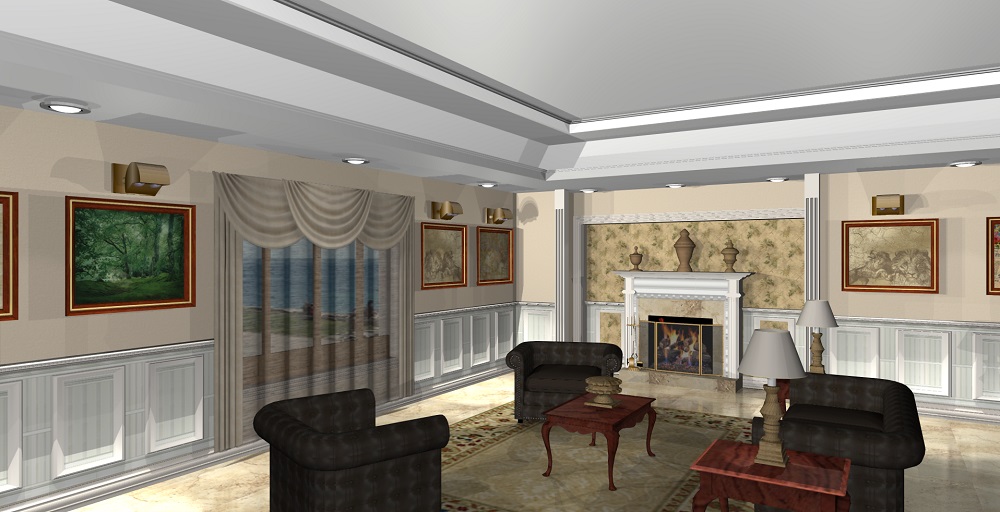
See the amazing results!