How to create the topography or topographical plan for a plot of land?
Architect 3D Tutorials
To build a house or design your garden, you need to take into account the elevation of your plot of land – in other words, the topography. The easy-to-use architecture software for everyone, Architect 3D©, provides you with the tools you need to draw a plan or a topography map for different types of terrain.
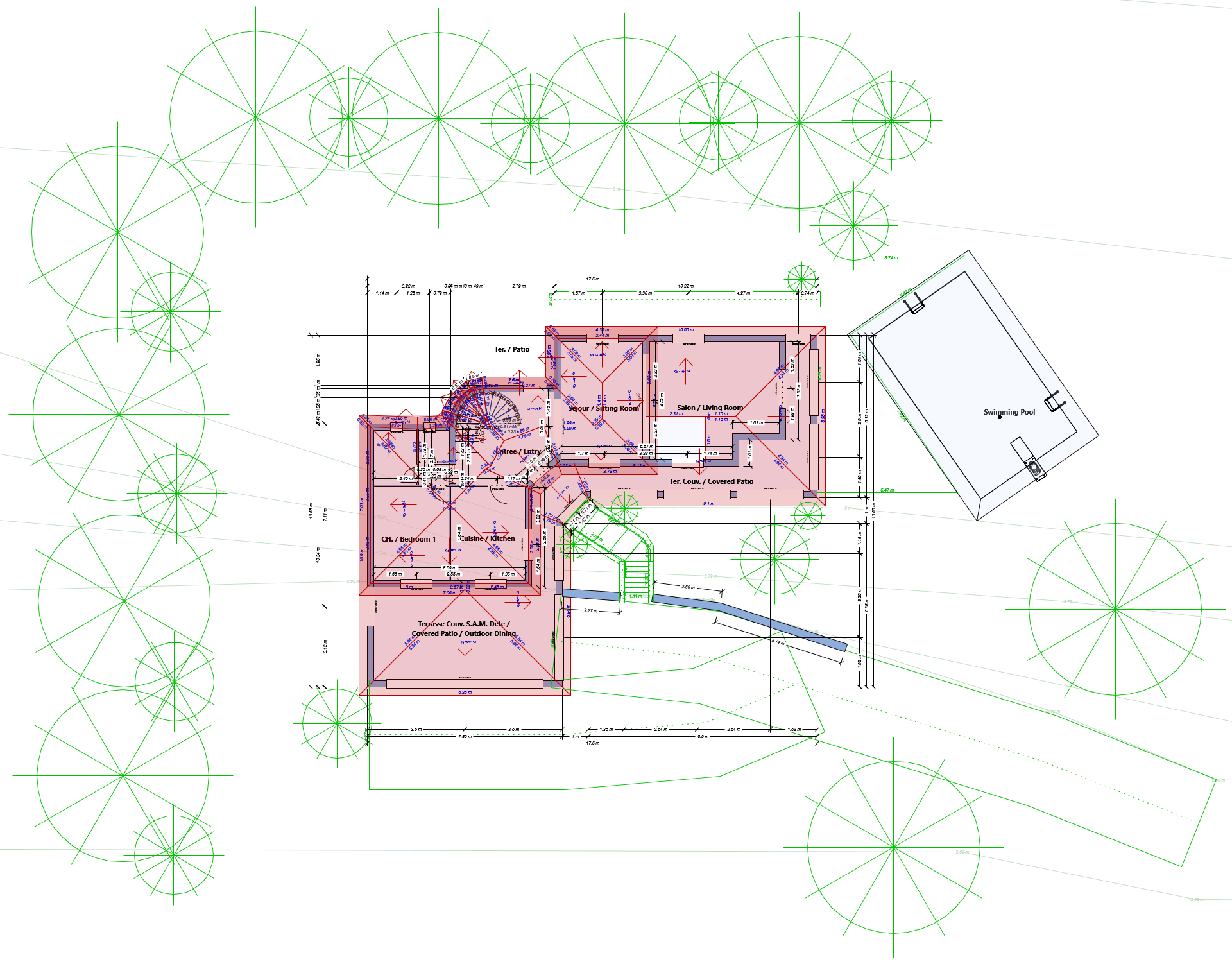
Architect 3D© includes special tools for illustrating the topography of a plot of land: draw contour lines (level curves) that share the same elevation and position the sloping sections. The topography design tools are easy to use: choose a general contour shape, then define the elevation of these contour lines to recreate the exact elevation of your plot.
Draw the topographical plan for a plot of land in 3 steps:
Step 1: Draw the topography lines
- On the Landscape tab, click on the Topography Line

- Via the Properties section on the right, select the drawing method Oval from Center.
- Click on the left mouse button and drag the cursor to define the desired shape. The extendable line that appears follows the movement of the cursor.

- Release the mouse button to position it.
In the following step, you can define the elevation parameters of these topography lines.
Step 2: Define the elevation of the topography lines
To make your topography work easier, open the 3D view window to display the 2D and 3D views. This way, you can work on the plan while viewing your changes in 3D and navigating to your 3D project at any time.
- Select a topography line in the design window, then enter the elevation value in the Properties section on the right.
The 1st zone is defined as zero to indicate the starting point of the slope.
- Click on Enter to confirm the value you entered.
- Repeat the same process to define the elevation of each topography line.

Once you’ve entered your different elevation values, you can see a sloped bank is drawn on your plot in the 3D view.
Step 3: Personalise and add features to your plot
After drawing the different topography lines to illustrate the contours of your plot of land, you can continue the topography plan using the tools offered within Architect 3D: add a ground fill region, create edging and refine the topography elements.
Adding a ground fill region
- On the Landscape tab, click on the Ground Fill Region
- In the design window, click on the left mouse button and drag to define your ground fill region: around your sloped bank in this example.
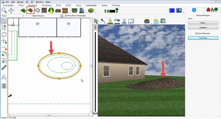
By default, mulch is used as the material for the ground fill region in order to preserve your soil or your future plants.
Creating an edging border
- Right click on the defined region you have drawn, then select Create Edging Border from the text menu that is displayed. The edging is illustrated with a default material that you can personalise using the software’s material library.
- From the 3D view window, click on the Select Objects in 3D button, then position your cursor on your edging. The Edging Properties section is displayed on the right.
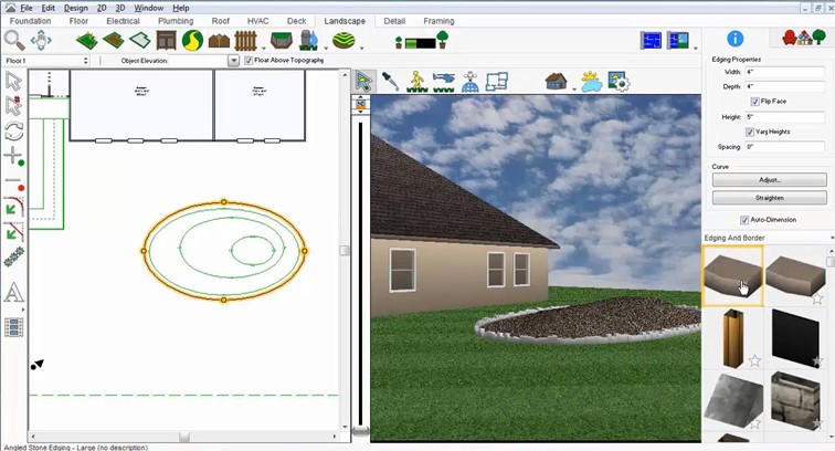
- Select a different material around the new sloped bank and personalise its appearance if necessary.
You can continue to modify the topography and add a slope lot section.
Including a slope lot section
- On the Landscape tab, click on the Slope Lot Section
- In the Properties section, define the starting altitude as 0.
- Position the cursor to indicate the start of the slope, keep the left mouse button pressed and drag the cursor to indicate the end of the slope. The slope angle between these two points is displayed in the Properties
You can modify these different drawing elements for the topography at any time, and you’re free to personalise the materials used in designing your plot of land.


