


How to draw a wooden mountain chalet in Architect 3D©
Architect 3D Tutorials
Do you dream of building a wooden chalet or house in the mountains where you can spend precious moments with family or friends, enjoy winter sports, go hiking in the summer and breathe in the fresh air? With Architect 3D© you can draw the plan of your wooden chalet or house in 2D, view it in 3D and make annotations… This simple and intuitive software offers all the tools you need to complete your design projects for your future home in the mountains.
Ecological, economical and authentic, wood is often the preferred material for building or covering a house in a mountainous location. This Architect 3D© tutorial will help you design the plans of your wooden chalet or house, step by step.
First of all, you need to define the following depending on the size of your family, your budget and your ideas:
- Surface area in square metres per floor
- Number of floors
- Total number of rooms in the wooden chalet or house
Designing plans for a mountain house requires preparation. We recommend that you start with the ground plan, the living area that is used the most, then move onto the floors.
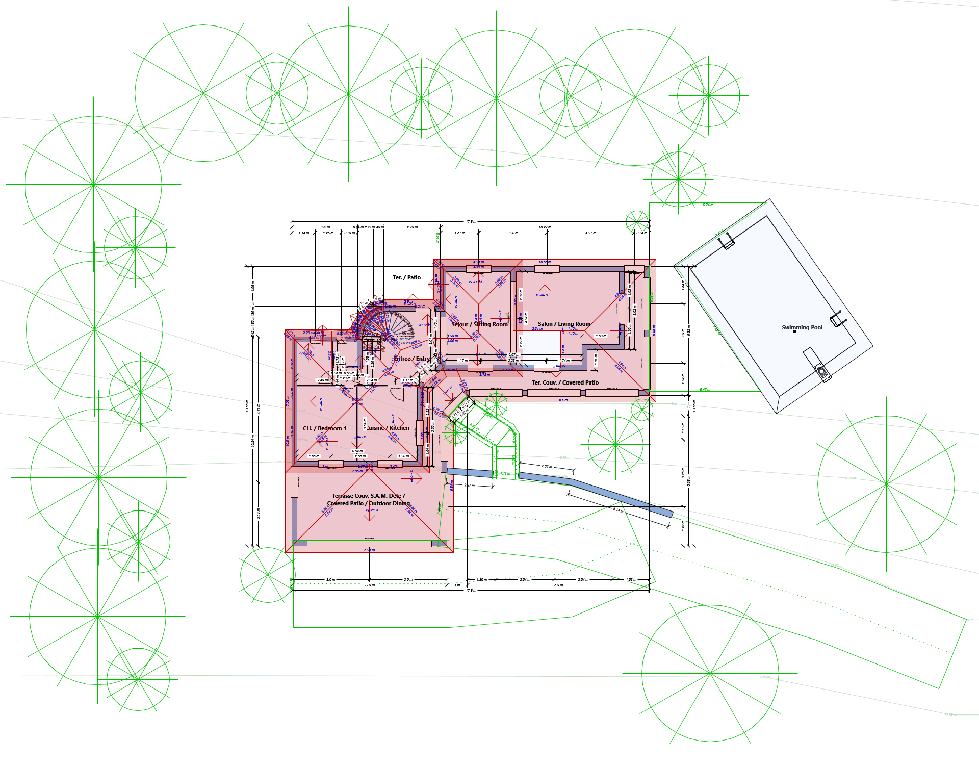
Designing ground plans and floor plans for a mountain house
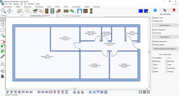
Drawing the ground plan for your wooden house in Architect 3D© is really easy. All you need to do is start the software and open the Quick Start module to quickly drag and drop the rooms and position them on the plan. The most common shape is rectangular:

You can create your rooms in just a few minutes. And you can change this plan of course.
Before you move onto the first floor, don’t forget to configure its height.
You can also modify the heights during the project if you haven’t yet specified the floor elevations.
Configuring the heights of the floors in a wooden house
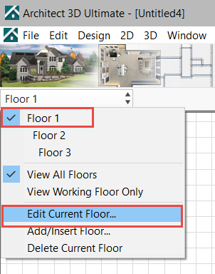
- To configure the heights, click on Floor 1 and select Edit Current Floor:


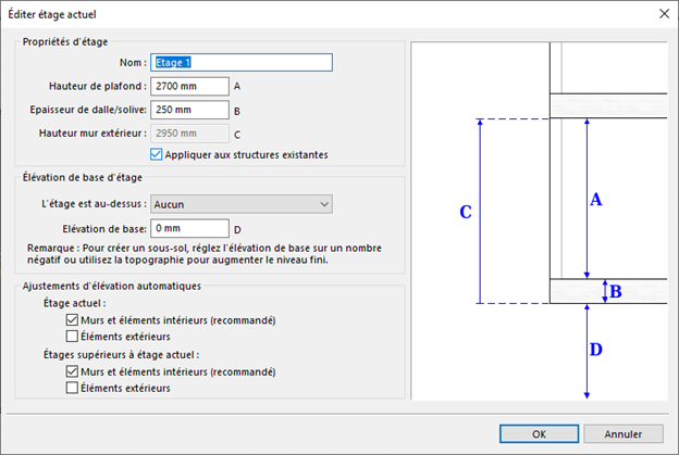
- Configure the parameters and click on OK.
Then select Floor 2 and configure the parameters for floor 2. Repeat steps 1 and 2 depending on the number of planned floors.
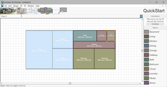
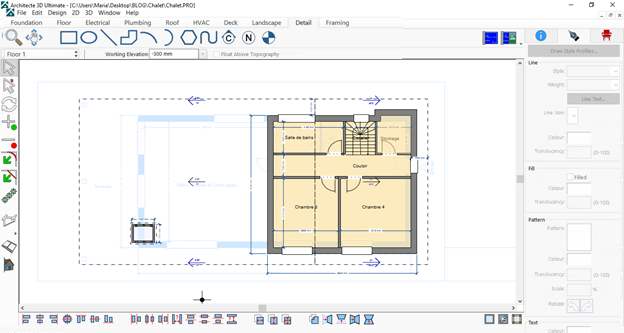
Now position the rooms on the second floor by dragging them from the right-hand list and dropping them on the plan. The plan for the first floor is visible as a layer:

Note: You can name the rooms in the next step.
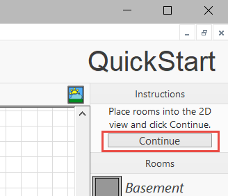
When you’re happy with the layout of your rooms, click on the Continue button at the top right of the screen to view the plan in 2D.
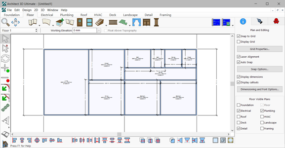
Modifying the dimensions of the rooms in the house
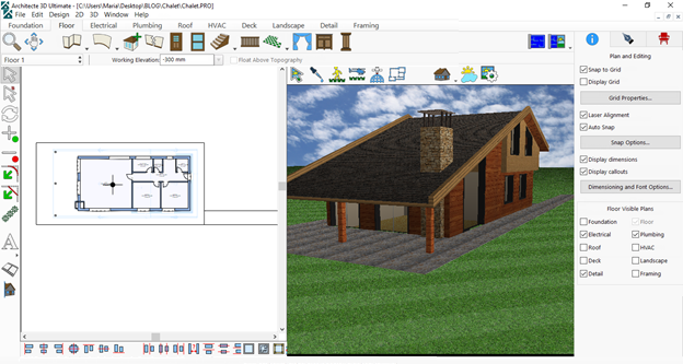
To hide the automatic dimensions and define the dimensions yourself in the required areas, go to the Design menu and select Options > Dimensioning and Fonts and deselect the Automatic Dimensions Visible field.

The plan is then instantly displayed without automatic dimensions.

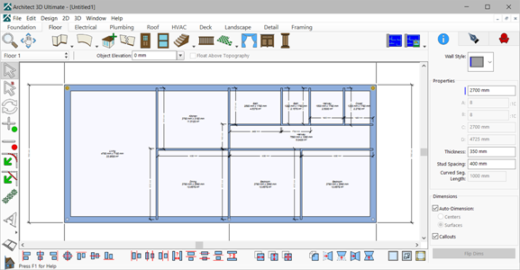
Modifying the thicknesses of the mountain house walls
By default, the software draws the walls in the Quick Start module with a thickness of 100 mm. To modify the thicknesses of the external walls, you can for example define 35 cm for the external walls and 12 cm for the internal walls. To do this:
- Select an external wall.
- Modify the thickness in the Information window.
- Press the Enter key on your keyboard.
The software will automatically modify the thickness of all the external walls.
External walls:
Internal walls:
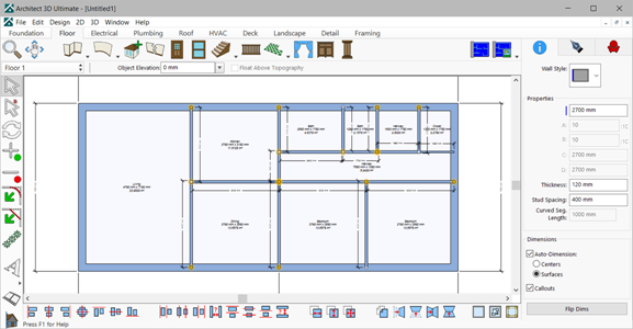
Tip:
To select multiple walls simultaneously, keep the SHIFT key on your keyboard pressed and select the walls that you want to modify.
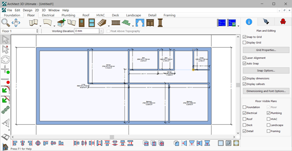
At this stage, some adjustments are needed on the plan, because the connection of certain walls will no longer be correct. To do this, drag the end points of the walls to perfect the traces.
Adding doors to the plan of your mountain house
You can now add doors to your wooden house. To do this:
- Select the Door tool from the Floor
- Choose a style of door from the list.
Place it in the desired position on the 2D plan.
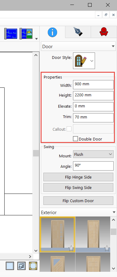
You can now select the door to indicate its height and width, then press the Enter key to validate the new dimensions.

You can add windows in the same way.
We recommend that you position the roofs beforehand so that the windows are well placed according to the shape of the house.
Placing a roof on the chalet/mountain house
A sloped roof style with two planes or two sections is very common for mountain houses and chalets. The two sections cannot have different surfaces:
- As this is a house with two floors, check that Floor 2 is actually selected.
- Click on Roof and select the Freehand Roof
- Position one plane by drawing a rectangle point by point: click to position the different points of the rectangle, then double click to finalise the trace of the roof.
Before you do this, place the lines that will guide you when positioning the roof.
Placing the lines using the trace to position the roof
The roof doesn’t follow the external walls but has eaves that are typical of large chalets. You can create eaves measuring 1 metre, similar to in this example. Using the Detail tool, place the lines at a distance of 1 m from the external walls that will serve as guide lines to help you trace the roof:
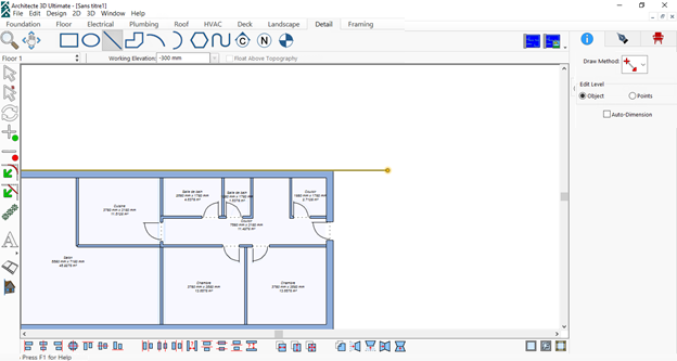
1. In the Detail tab, select the Line
2. From the Edit menu, choose the Move
3. Enter 1000 in the Y Axis field to move the line upwards:
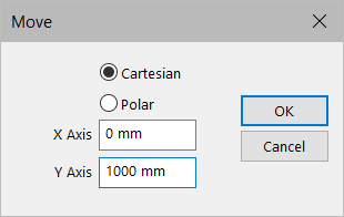
4. Follow the same steps for all the sides.
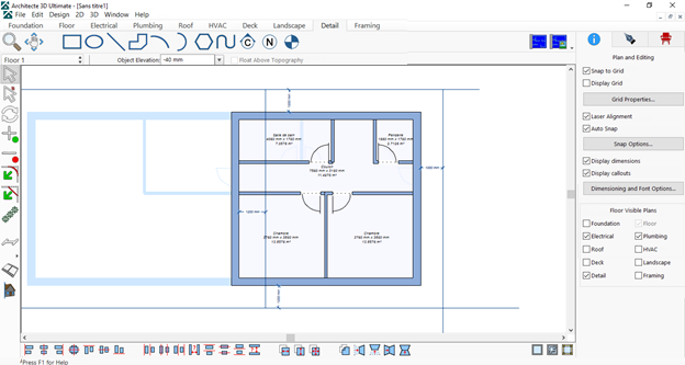
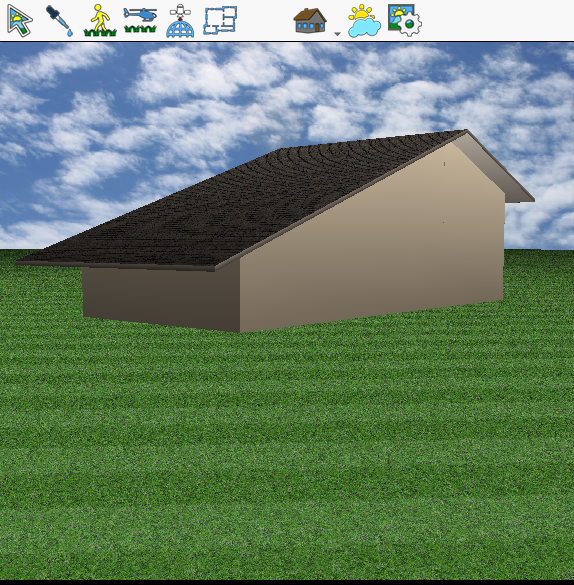
Now you’re ready to put the roof in place:
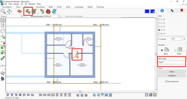
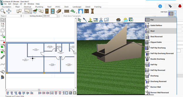
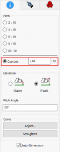
Adjusting the slope and the elevations
If you notice that the slope doesn’t have the correct incline when placing the rectangle:
- Rotate the arrow to change the direction of the slope.
- Then modify the angle of the slope by indicating the desired value.
- Press the Enter key on your keyboard to validate your modification.
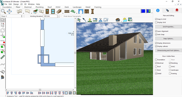
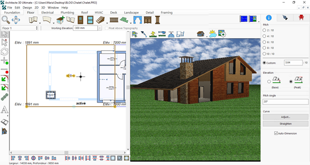
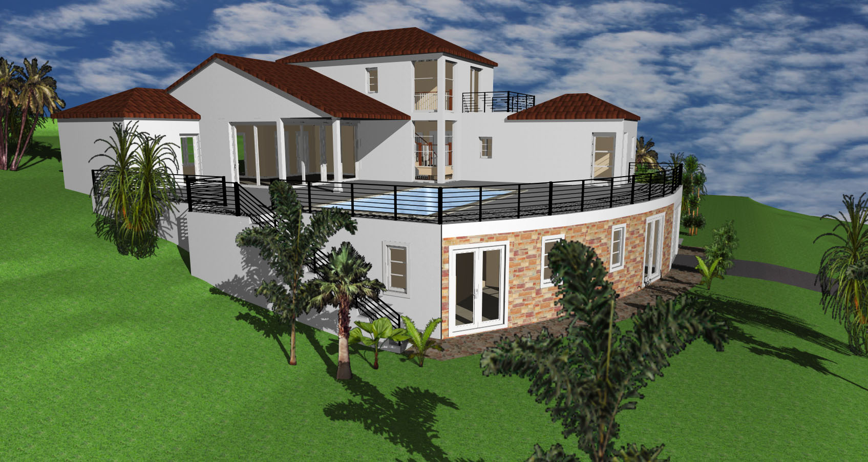
Now it’s time to view your mountain house project in 3D!
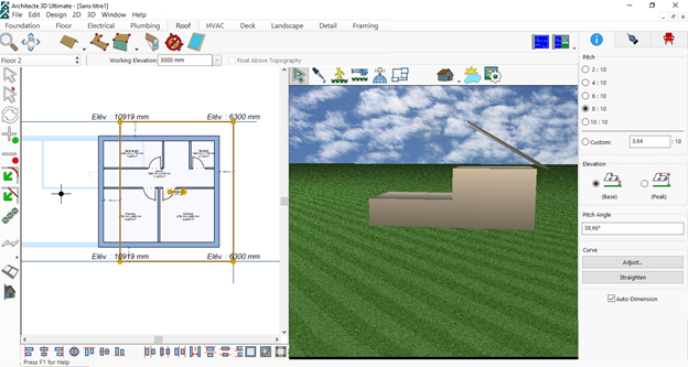
By working with a half screen view, you can make modifications simultaneously on the 2D and 3D plans.
Thanks to the 3D view, you can see that the roof isn’t positioned correctly. This means you need to reduce its height.
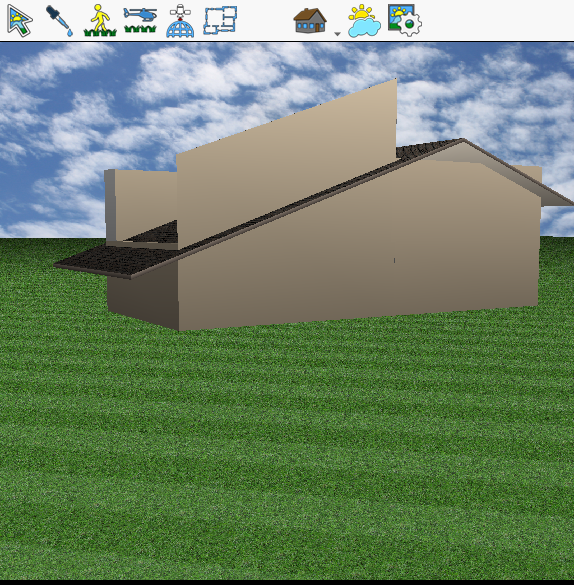
If you follow the example described in this tutorial, you can see the elevations of each point on the plan. The lowest part is currently 6,300 mm from level 0, which is very high. The house doesn’t look like a chalet yet. To solve this, lower the elevation via the Object Elevation menu.
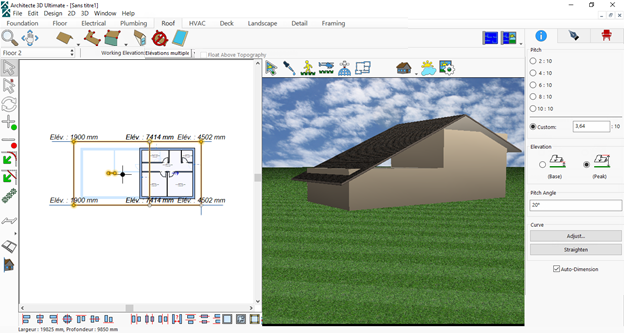
Once you’ve adjusted the heights of the two sections, the roof is in the correct position. You can now delete the guide lines that you added.
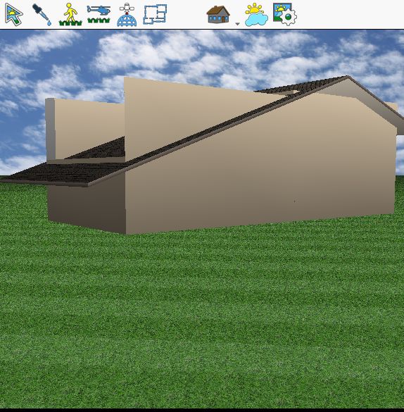
Adjusting the walls of your mountain house
Now you need to make some modifications to the walls so they’re well attached to the roof. To do this, don’t hesitate to increase the height of the walls of floor 1 so they reach the highest parts of the roof:
Then select a wall, click on Wall Style on the Information tab and choose the Shed option.
All you have to do now is indicate the correct parameters so that the wall is positioned beneath the roof. You need to modify the angle:
- Select the roof and check the value of the slope.

In this example, the value is 3.64:10.
2. Re-select the wall for which you’ve chosen the Shed option and enter the same value.
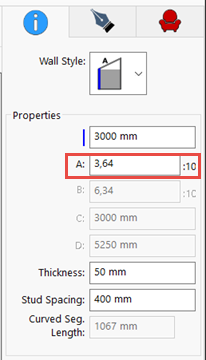
Now you have to modify the height of the wall.
You can follow the same procedure for all the walls.
Now you can add the windows. The procedure is identical to that described for the doors.

All the windows are in place.
Adding a chimney to the mountain chalet
What good is a chalet without an all-important chimney?
Use the Wall tool to draw a chimney.
The design is ready but there are a few more details and materials to add to the facade. As your house will be a wooden chalet, this aspect needs to be clearly visible in the project.
Covering your chalet
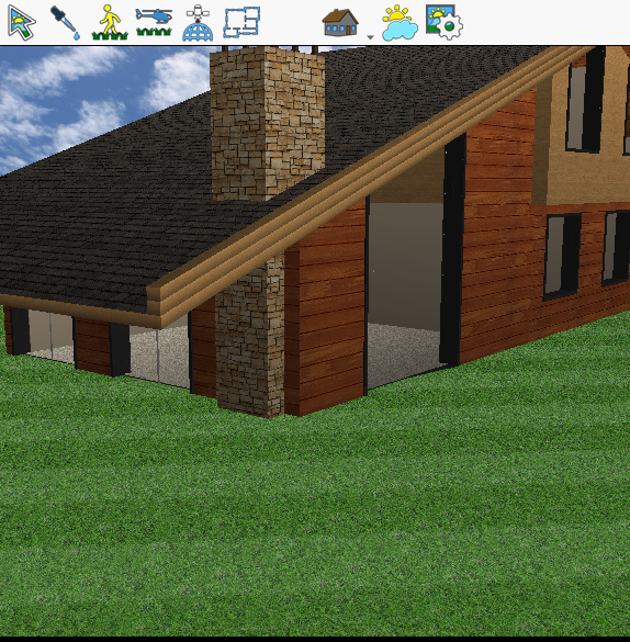
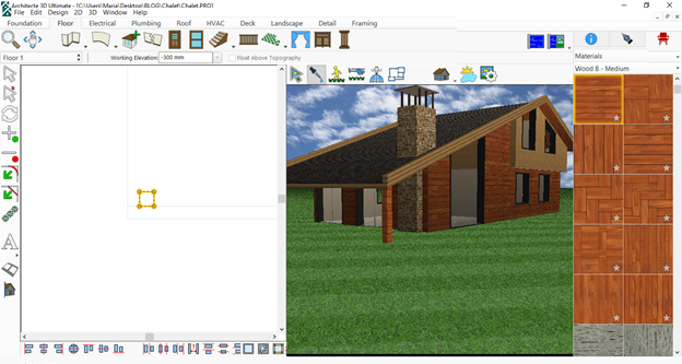
Applying wooden and stone materials
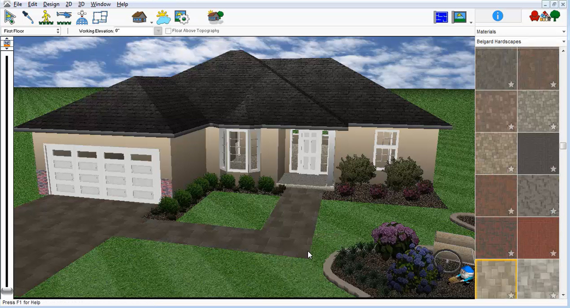
To add materials, click on the Materials library to choose a type of wood, then apply the wood by simply dragging and dropping it onto the 3D view.
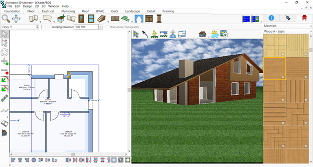
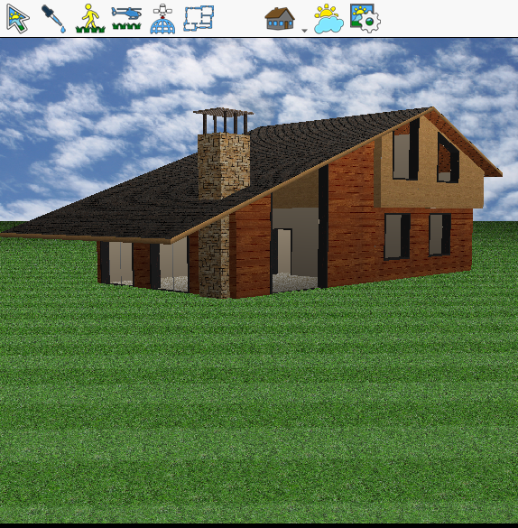
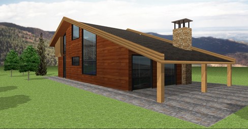
The wood is added. You can now add stone to the chimney using the chimney finishes and complete the covering of your chalet.

To copy this example and finish the chimney, you need to add six columns and a floor using the Floor tool. Then you can define the required height of the columns.
Applying the colours
You can also change the colour of the windows and doors via the Colours library by simply dragging and dropping the desired colour onto your openings. Here’s the result:
Adding an edge to the roof
You can add edges to the roof. To do this, go to the Roof tab.
- Select a section and choose the menu path Edit > Duplicate.
The parameter value for the offset is 0, as the roof needs to be above that which is already present.
- To copy the example in this tutorial, change the size of the roof to find out the size of the edge: enter 7150 mm via the Object Elevation.

You can see that the roof has doubled and the edge has been added. If you want it to be even higher, duplicate the section of the roof again and follow the same steps as above.
You can redo the steps for all the sections of the roof / three more times.
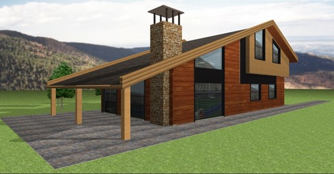
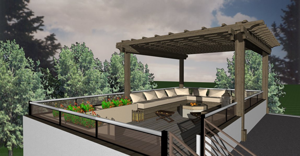
You can continue to personalise your chalet and add columns to the deck.
Adding and personalising columns
To do this, use the columns included in the Furnishings library:
- In the Furnishings library select Building Elements > Columns – Components > Column Square Full.
Apply the material via the Materials Library.
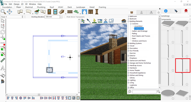
Tip: Using the pipette, you can easily select an existing material in the 3D view so you don’t have to search for it in the library each time.
Duplicate the column twice and distribute the two other columns beneath the roof.

The chalet is now placed directly on the grass, which must not be the case.
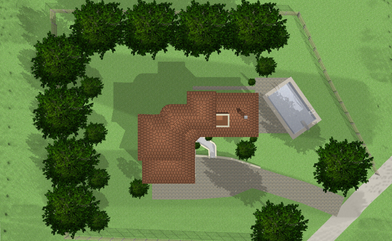
Use the tools in the Deck and Landscape tabs to create a suitable environment, draw terraces and pathways around the house.
If you want to use different materials, draw each part as a separate tile so you can then easily apply the materials.
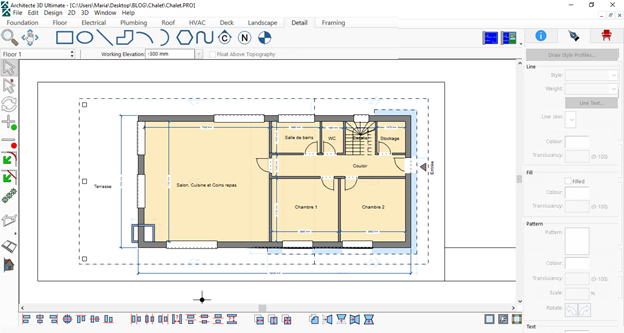
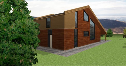
To personalise the details on your plan, modify the wall colours (grey in the example) and personalise the lines for the roof using whichever line type you choose.
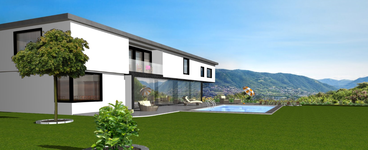
The chalet design is almost finished. Now all you need to do is create the 3D views and add a pleasant environment around your chalet.
Working in the 3D view
If you have photos of your plot of land, you can import them using the PhotoView Power Tool.
Using PhotoView
- Select the Design menu then launch PowerTool > PhotoView Editor.
- From PhotoView, select menu path File > Import to choose the photo of your land.
The Architect 3D© software also allows you to create facades from the 3D view.
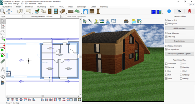
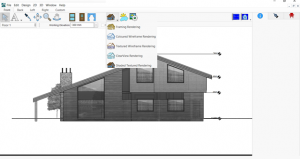
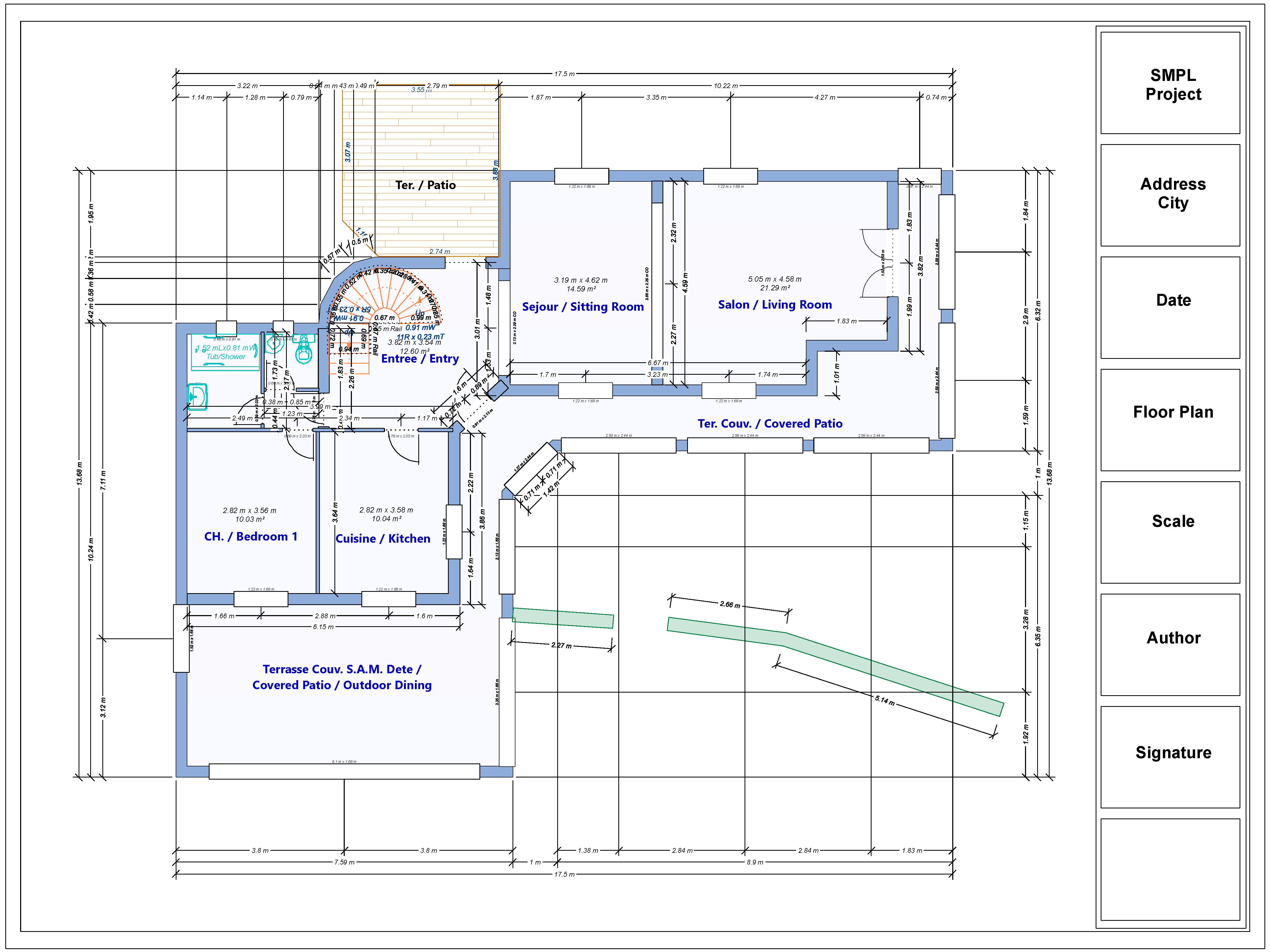
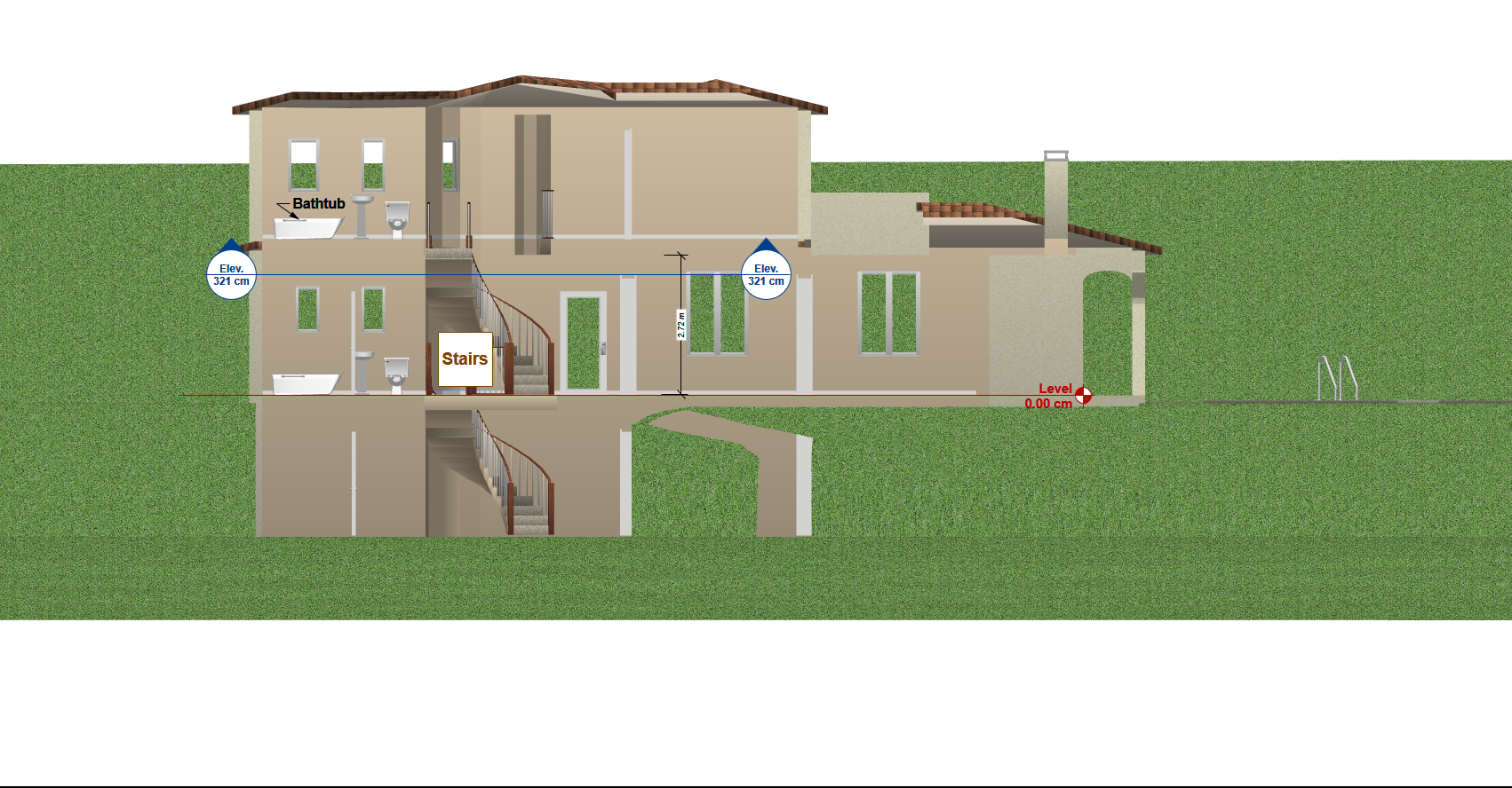
Creating the facade plans
- To do this, select Elevation View from the display options (also called view icons).
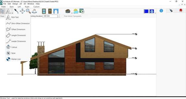
 In this view, you can add dimensions, text and markers.
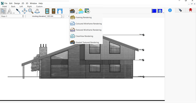
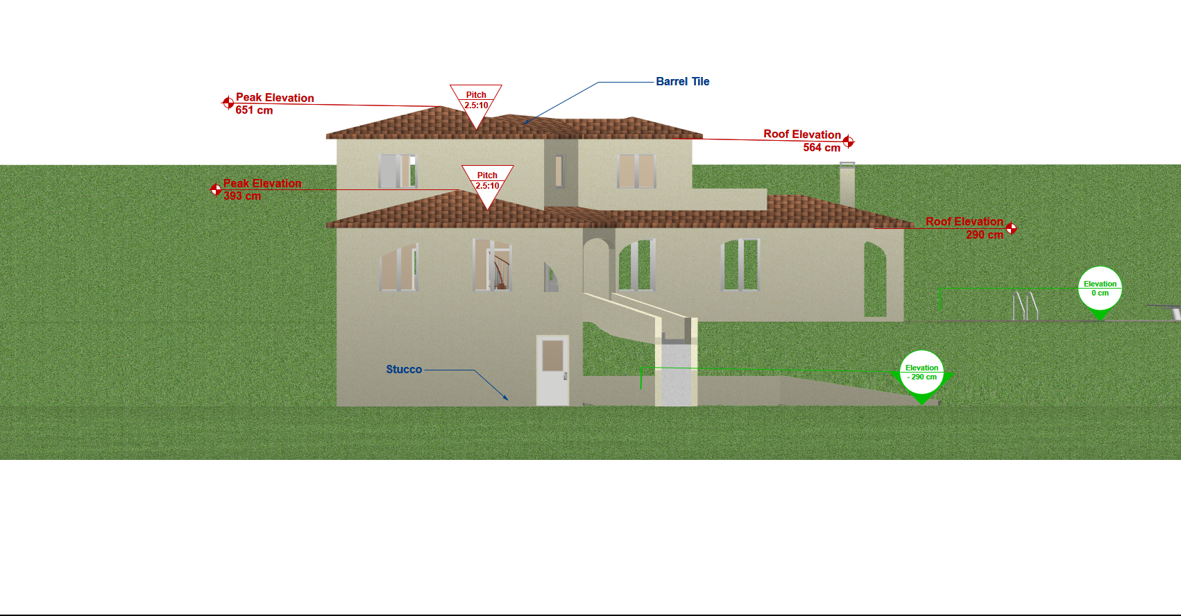
- If you need to display a view without materials, select the ClearView Rendering mode:
3. Select Front, Back, Left and Right to obtain the different elevation views (or facade plans) in two clicks.This tutorial gives details on how to design a wooden chalet, but is it possible to draw a chalet with logs in Architect 3D©?
If you want to design a chalet with logs, you can also do this in the Architect 3D© software. The tools you need are available in the Furnishings library, in the LogHome (Wooden Structures) section.
The only difference is simply how you design the house, as you use furnishings instead of walls. Then you need to define the parameters of each furnishing using the appropriate dimensions to complete your project.
- If you need to display a view without materials, select the ClearView Rendering mode: