


Tutorial · Architect 3D 26 for Windows
How to create cross sections with Architect 3D
Updated · About 5 minutes
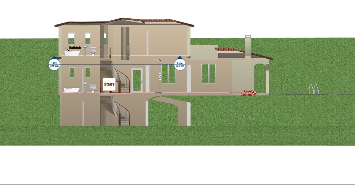
Written for Architect 3D 26 for Windows. The Mac edition has similar tools, though some menu names differ.
A cross section shows the inside of a building as if it had been cut through by a vertical plane. Depending on your project and local requirements it shows floor and ceiling levels, the roof, and how the building sits on the ground.
Finish the floor plans and roofs first. The section is cut from the 3D model.
Step 1: Draw a cutaway line
- On the Edit toolbar, click the 3D Cutaway tool.
- On the Properties tab, set the Direction to Vertical.
- Click and drag a line across the building, and across any exterior elements you want in the section.
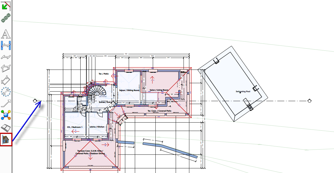
The arrows on the line show which way you are looking. Use Flip Cutaway Direction on the Properties tab to look the other way. You can draw several cutaway lines, but only one is active at a time.
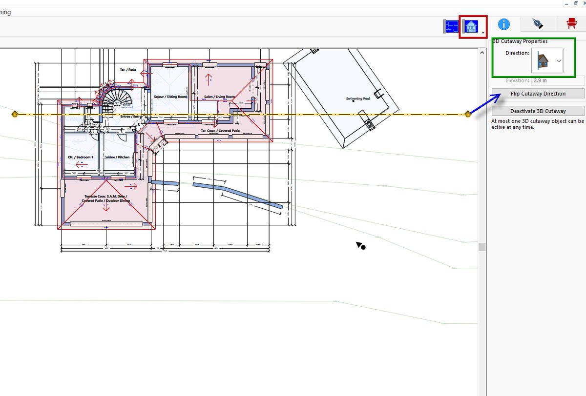
Step 2: View and annotate the section
- Click Elevation View to see the section.
- Choose Front, Back, Left or Right from the predefined views if needed.
- Add the information with the same tools as for an elevation: Rich Text, the dimension tools, Leader Dimension, Callout, Note and Marker Line.
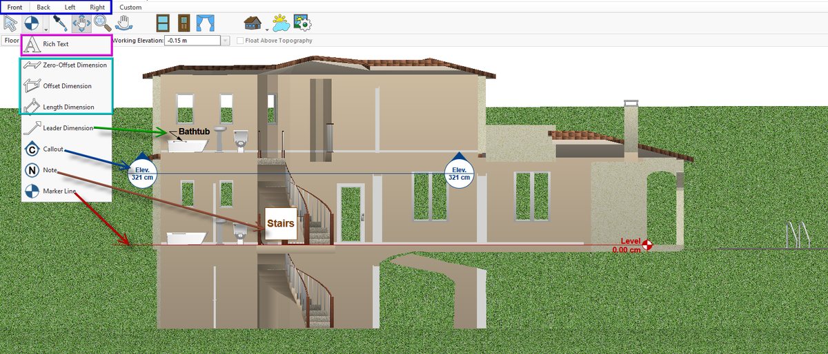
As with elevations, annotations belong to the view they were added in.
Step 3: Switch to a line drawing and print
For a section that reads as a line drawing, choose the ClearView rendering style. It makes interior dimensions easier to mark.
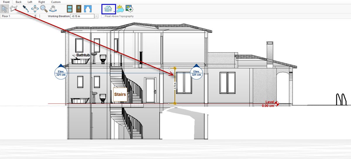
When the section is complete, print or export it.
Editions: the 3D Cutaway tool is in every Windows edition except Express. For detailed construction sections, such as wall build-ups or footings, Ultimate and Platinum also include the Section Detailer.