How to Create Floor Plans Using Architect 3D©
Architect 3D Tutorials
Create complete Floor Plans including the project information, labels and title blocks!
For permits purposes, the Floor Plans are intended to show the layout, openings and dimensions of the project as well as the different settings and code compliances required by the office granting the permit. These elements may vary for different locations.
To start with the Floor Plan development using Architect 3D© you have several options:
-
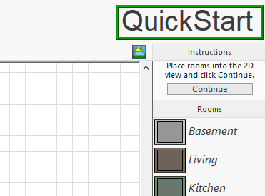
Option 1: If you are designing your own project, you can create the desired room layout using the Quick Start tool (outlined in green in the image below)
-
Option 2 you can draw your plan using the Wall Tools (Floor Tab), outlined in red in the image below. Define the walls shape and elevation.

-
Option 3: If you are using a premade project and you have this plan as a jpg or bmp or png drawing, just proceed to import the image and trace the lines.
To do this, use Design (outlined in red in the image below) => Floor Plan Trace Properties (outlined in green in the image below) => choose the image using Set image (pointed with a yellow arrow in the image below) => the trace image will appear in the preview window (pointed with a blue arrow in the image below).
You can resize the image by percentage or size. Once you have the image in the workspace, proceed to draw the walls as indicated on Option 2.

-
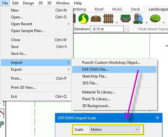
Option 4: If you have a DXF / DWF plan, you can import this file directly to your Architect 3D©.
To do this, open your program => File => Import => DXF / DWG File => the menu will open (pointed with a magenta arrow in the image below). It is important that you set the correct scale (outlined in yellow in the image below). Once you imported the plan, proceed to convert the lines and shapes to Architect 3D© components.
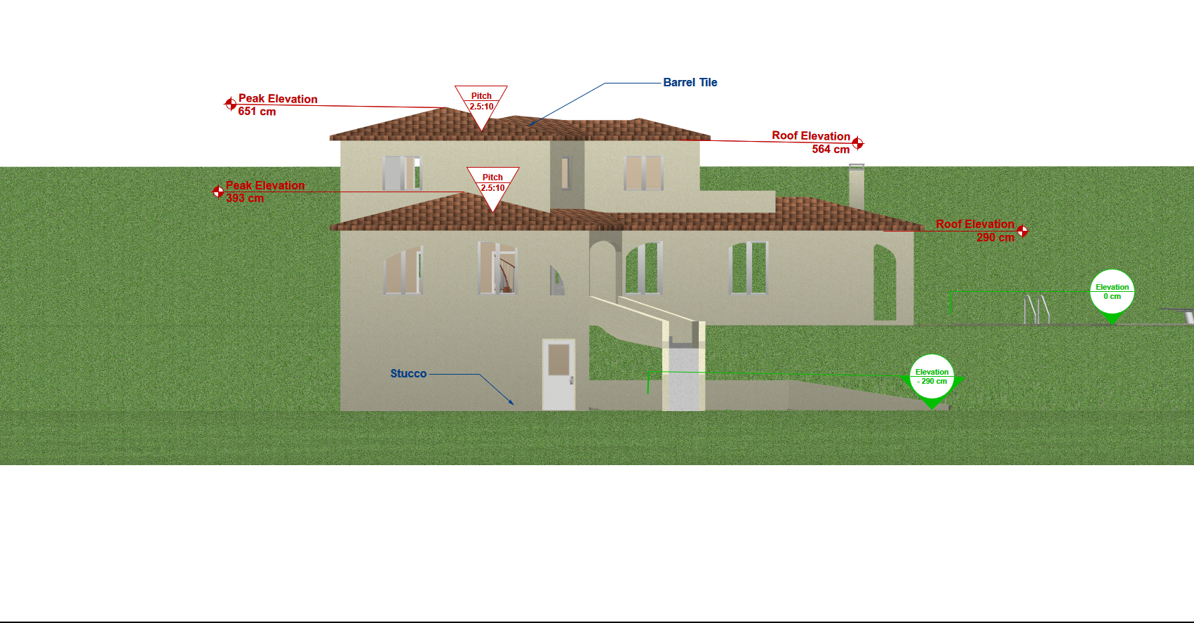
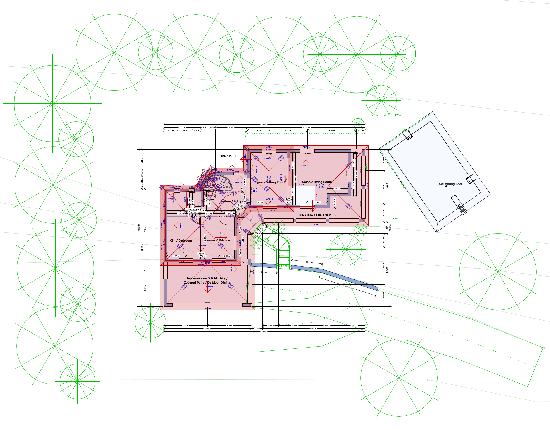
Once the walls, floors, and elevations of the rooms are ready, review the different dimensions: in the main menu go to Design => Options => Dimensions and Fonts (outlined in blue in the image below). Set the Automatic Dimensions as Visible and select the desired settings and fonts for the dimensions. Notice that the exterior dimensions are always surface to surface.
You can change the elements’ colors (pointed with a red arrow in the image below), fills and patterns (pointed with a green arrow in the image below) using the tools in the Draw Style tab. You can change the color of the texts by selecting them and using the text tool in the Draw Style tab (outlined in magenta in the image below).

Using the Doors and Windows Tools (Floor tab) insert these components with their individual dimensions. Selecting each door, (in the properties tab), you can set the hinge side, swing side, as well as the opening angle. It is also important to define if it is a simple or double door.
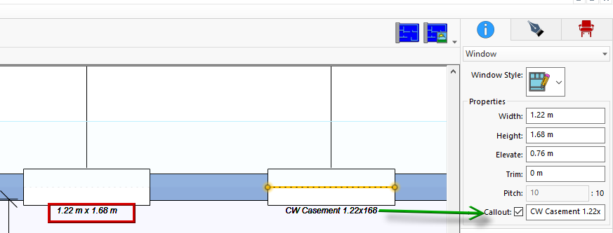
Both Doors and Windows allow annotations. By default, they show their dimensions (outlined in red in the image below). Optionally, you can set a callout with custom information (pointed with a green arrow in the image below).
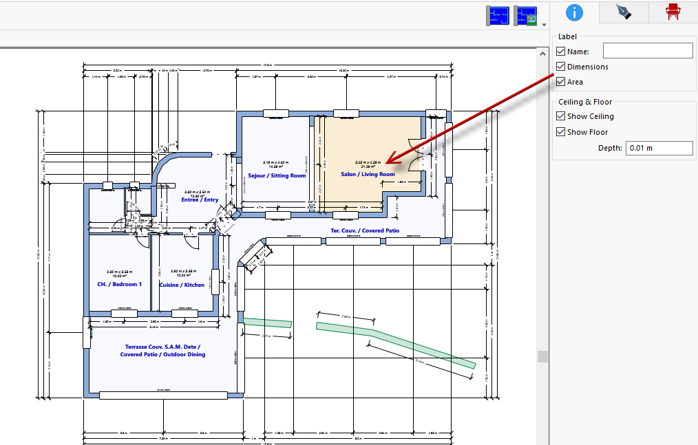
In each room, you must include a label. You can set the individual information labels by clicking in the center of the room. Then, in the Properties tab, you can define the name of the room, the dimensions as well as the area (pointed in red in the image below).
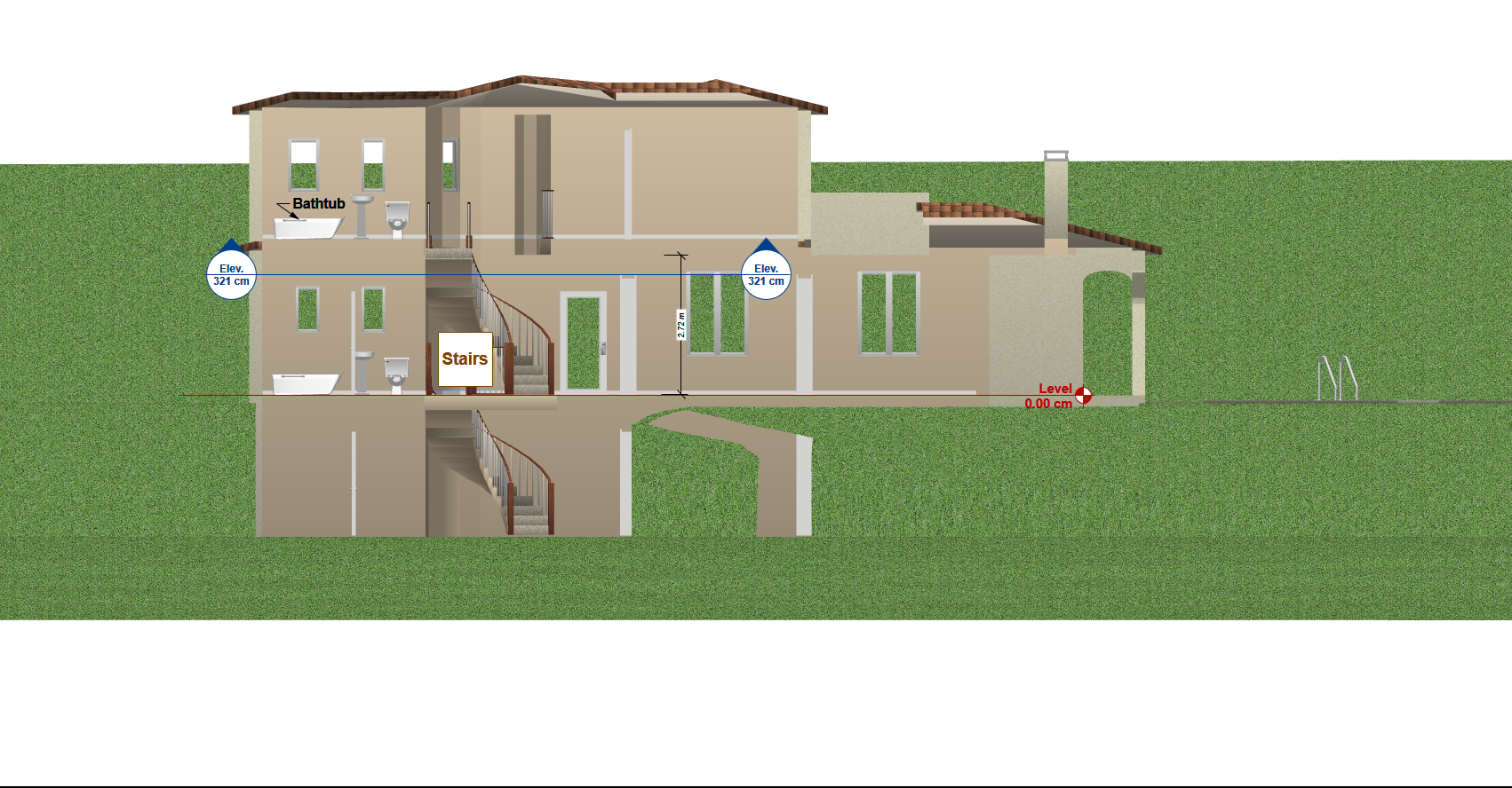
In the Plumbing tab, you will find the necessary fixtures to organize your bathroom, such as tub, shower, toilet, lavatory, etc (pointed with a blue arrow in the image below). In addition, it is important to mark the spaces, door openings, etc.
The internal stairs can be created with the Stair Tool (Floor Tool), outlined in green in the image below. Trace the stairs and define the different parameters such as Height and Width of the entire stair, Height and Depth of the steps. You can add handrails and skirt walls. Don’t forget to select the auto dimension option (pointed in green in the image below).
You can also include patios, decks, etc (pointed with a red arrow in the image below).

Optionally you can include a scaled frame so you can add the document information and print to scale, choosing the exact size of paper.
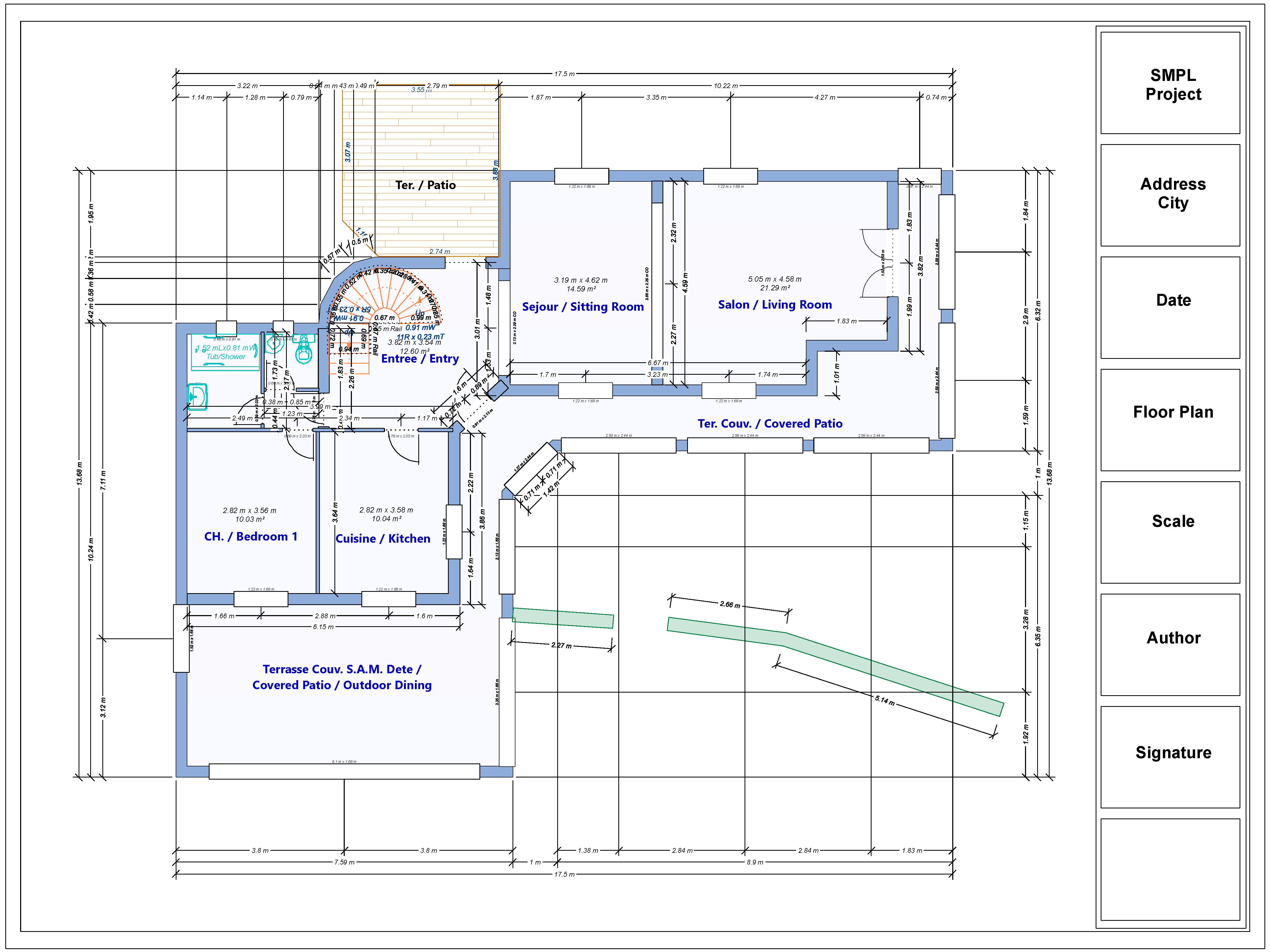
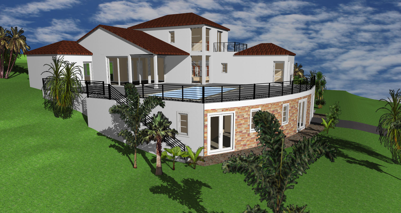
Your Floor Plan is ready!
As you can see, it is not a complicated task, that you can develop in no time following these tips. Happy project!