How to Create Cross Sections Using Architect 3D©-Planning permission
Architect 3D Tutorials
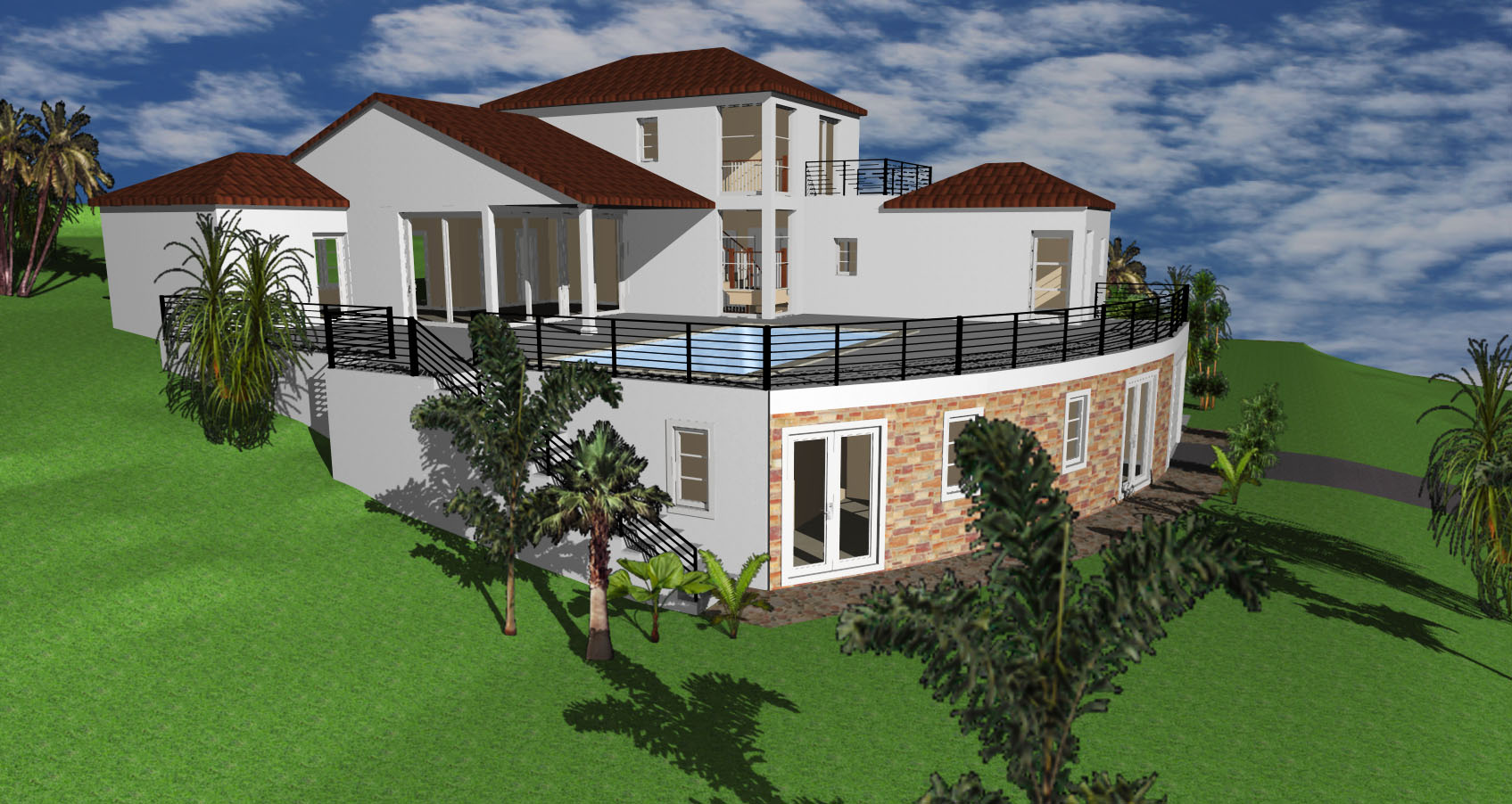
Cut your project in any angle and define the interior and exterior settings of your design. A Cross Section is a drawing showing interior of the building after cutting it with a vertical plane.
The Cross Sections include different type of information (such as elevations, roofs, exteriors elements, etc) depending on your project, the permit requirements and the location of your property.
Once your project is complete, including Floor Plans, Roof Plans, etc. you can develop the Cross Sections.
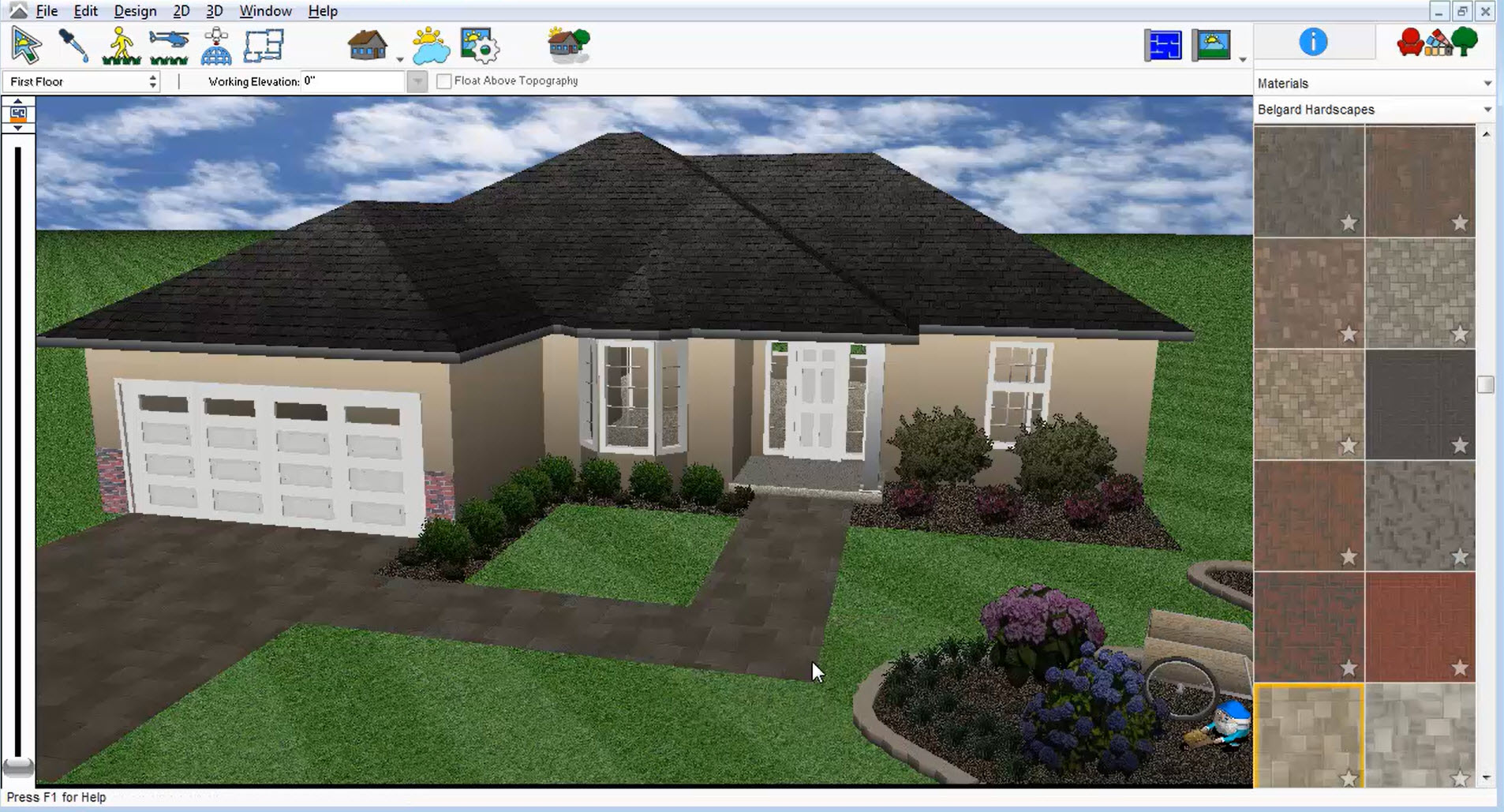
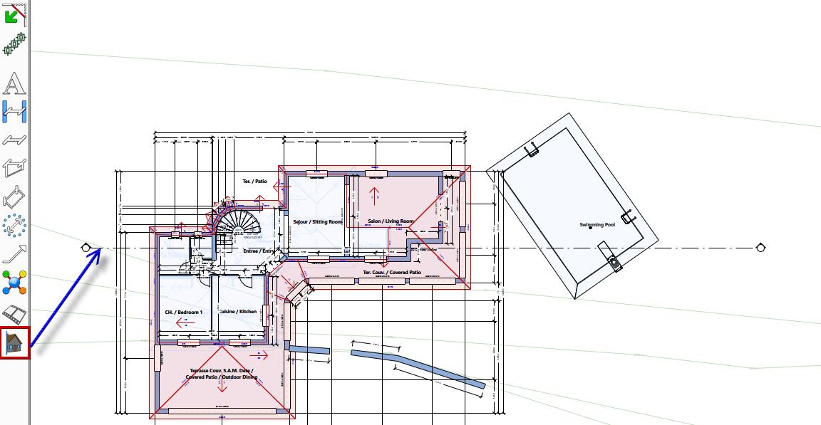
Step 1: your Architect 3D program includes a special tool to create Cross Sections called 3D Cutaway (outlined in red in the image below).
Using this tool, create a line across the building and exterior elements (pointed with a blue arrow in the image below).
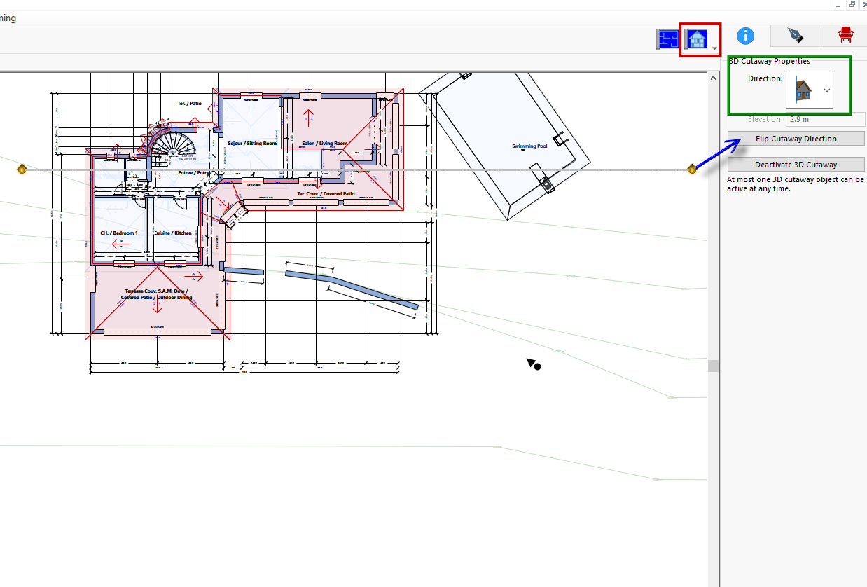
Once you trace the horizontal or vertical cutaway line, in the Properties bar (right of the screen), define the 3D Cutaway properties (outlined in green in the image below).
The cutaway arrows (in the cutaway line) show the direction of the view. Therefore, you can flip the view using the Flip Cutaway Direction button (pointed with a blue arrow in the image below).
If you add several cutaway lines, note that just one of them can be active at any time.
After you define the settings, you can visualize the Cross Section by selecting the Elevation View button (outlined in red in the image below).
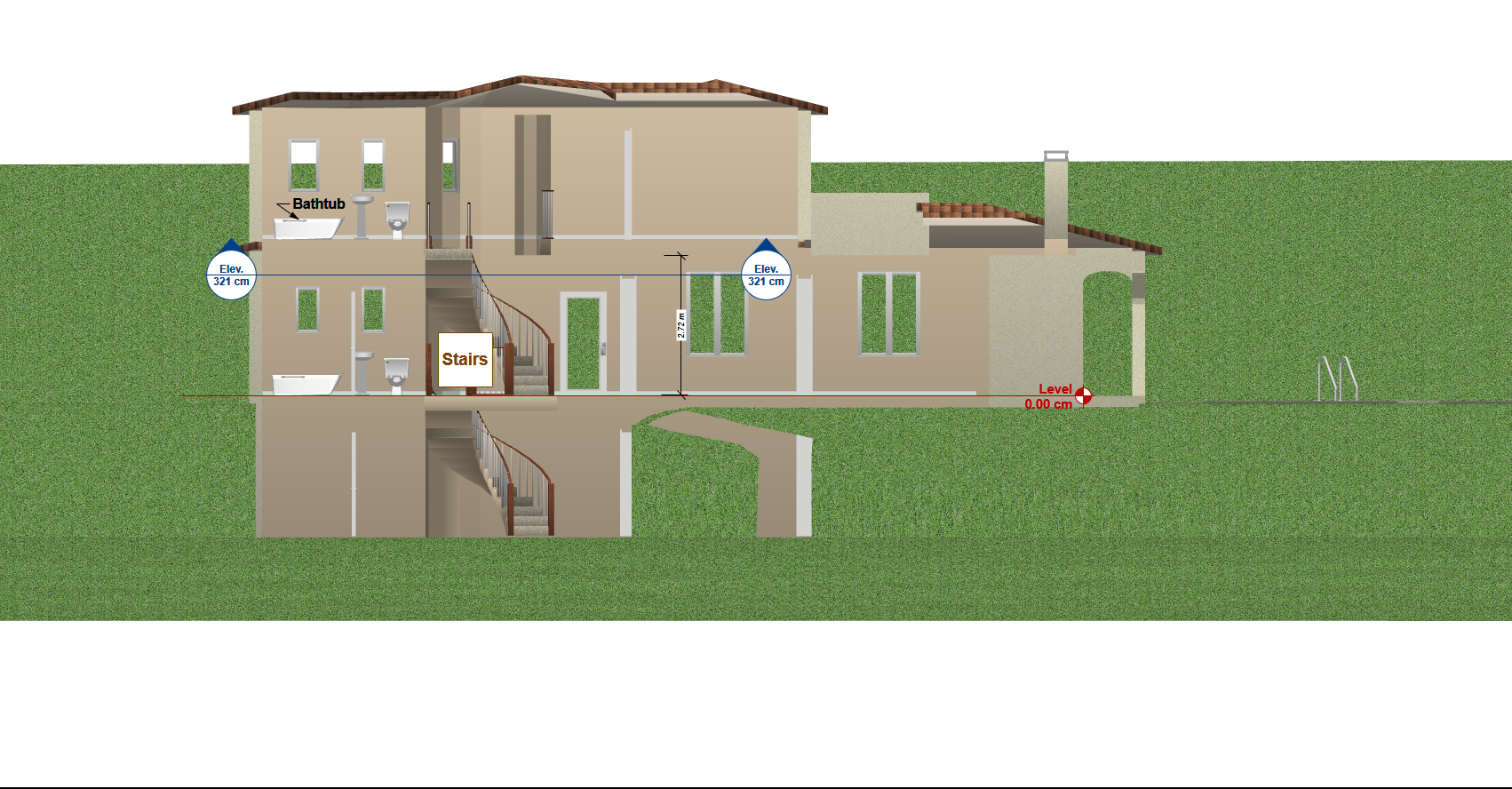
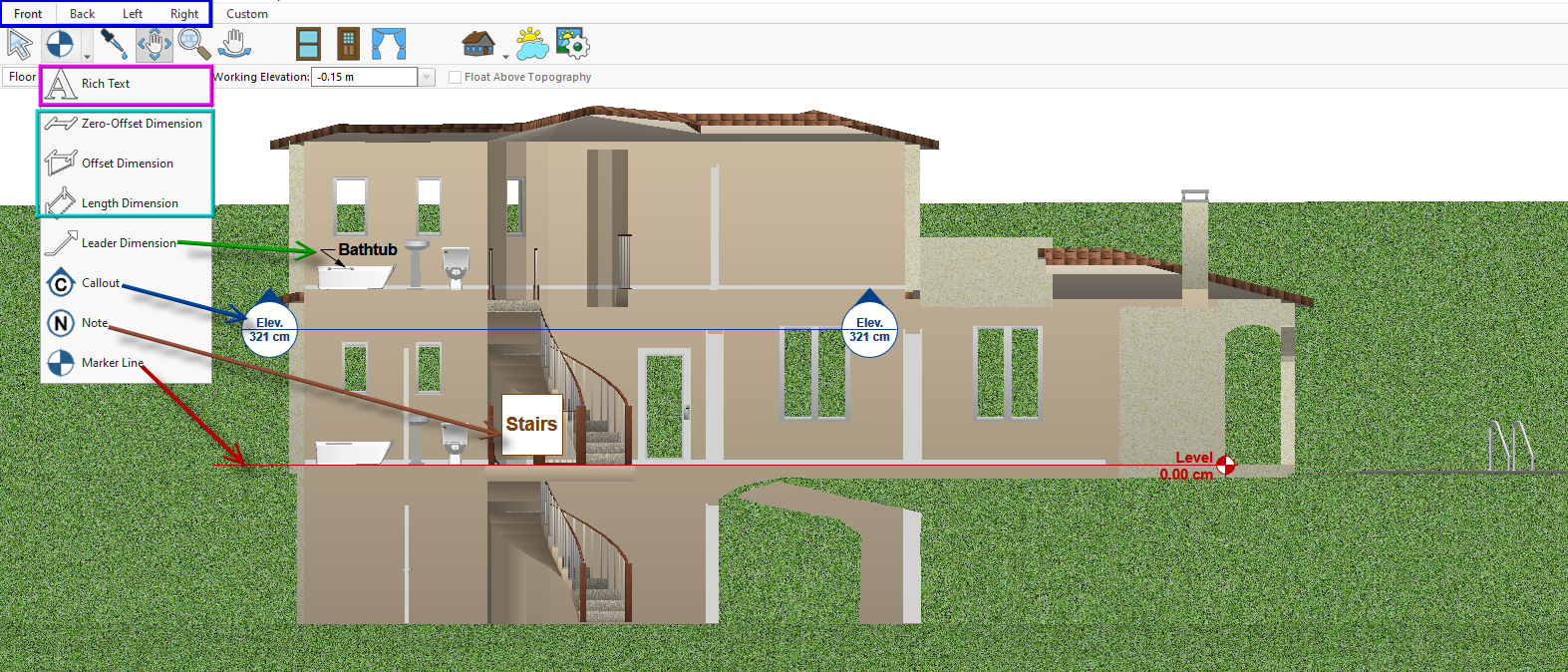
Step 2: once you visualize the Cross Section, you can define the image settings as well as the drawing information.
By default, the image will show the Front View (facing the south side of the lot), however, you can choose another view such as Back, Left or Right (outlined in blue in the image below).
Then, proceed to add the necessary information using these eight tools:
- Text boxes and labels can be created using the Rich Text tool (outlined in magenta in the image below).
- You can indicate any type of dimension using the three dimensions tools (outlined in cyan in the image below).
- Using the Leader Dimension tool, you can point to an element and add a text (pointed with a green arrow in the image below).
- The Callout tool (pointed with a blue arrow in the image below) is used to show crossed sections or lot levels and elevations.
- With the Note tool you can create different notes featuring different information, shapes, etc (pointed with a brown arrow in the image below).
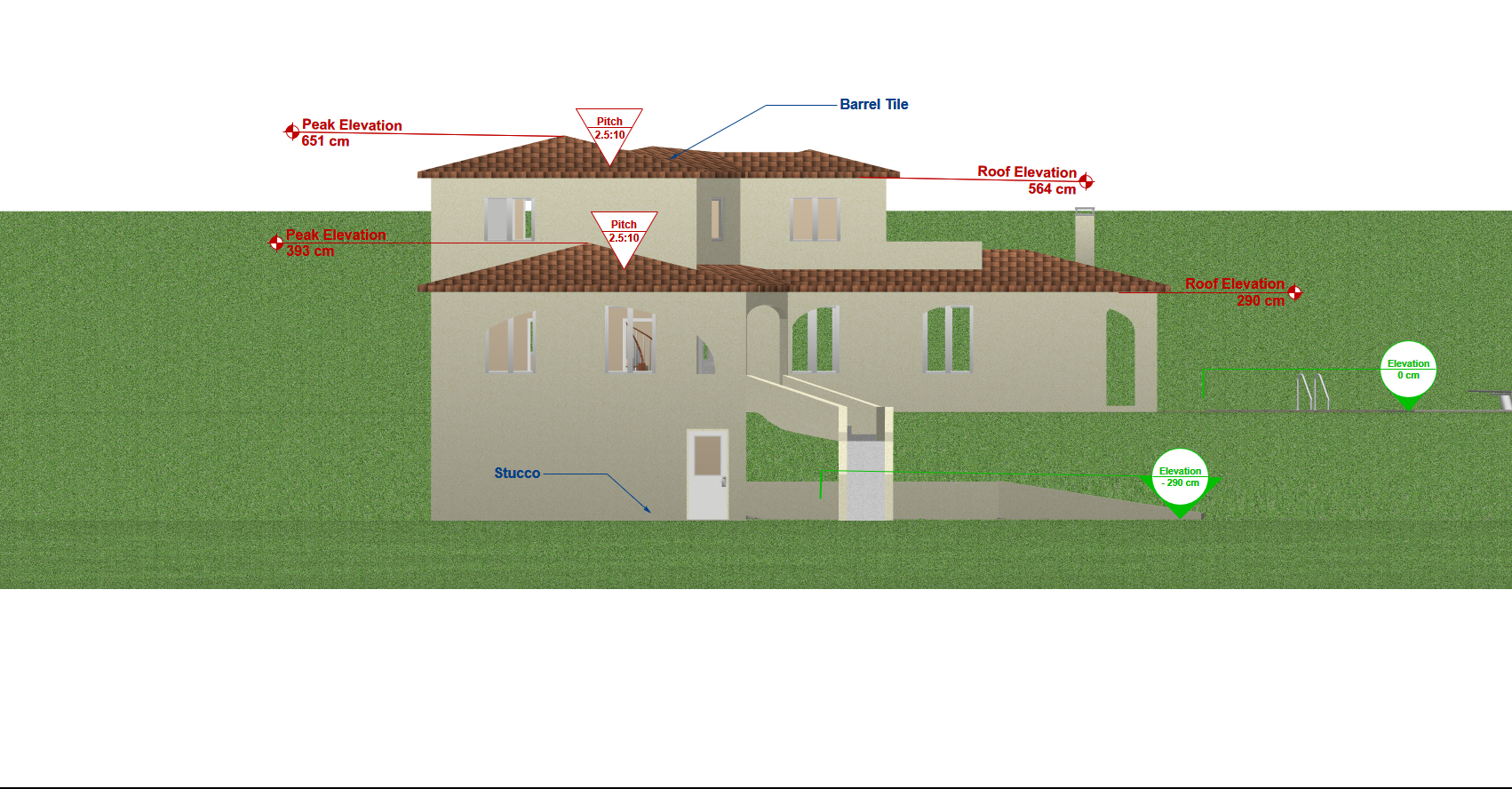
- The Marker tool is commonly used to indicate the different levels, heights and building elevations (pointed with a red arrow in the image below).
Note that any of the lines, texts, etc. developed with these tools can be customized by selecting them and changing the properties.
Also, notice that each annotation is part of that particular elevation view. If you change to a different view, you need to add new annotations.
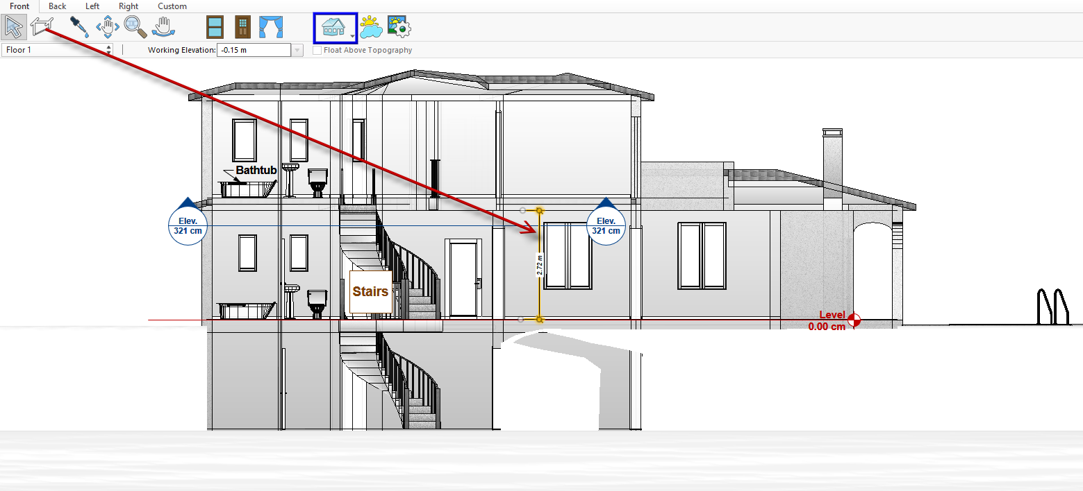
Your Architect 3D© program includes different rendering styles, therefore if you wish a Cross Section more focused on the lines, using the Rendering Style button (outlined in blue in the image below) you can select “Clearview Style”. This option is useful to mark internal dimensions (pointed with a red arrow in the image below).
Once you complete the information, you can proceed to export or print the finished Cross Section, as shown in the image below.